System and method for tracking the point of gaze of an observer

a technology of gaze tracking and system, applied in the field of system for tracking the point of gaze of an observer, can solve the problems of introducing latency in gaze tracking, user-specific calibration not being a realistic option, and system usage restricted to desktop use, so as to achieve the effect of only increasing the latency

Active Publication Date: 2013-01-03
KONINKLIJKE PHILIPS ELECTRONICS NV
View PDF49 Cites 70 Cited by
  • Summary
  • Abstract
  • Description
  • Claims
  • Application Information

AI Technical Summary

Benefits of technology

[0038]In embodiments, the system comprises means to provide more than one marker and means to identify the markers and couple the markers to one or more eyes of observers. The advantage of this embodiment of the system is that the latency only increases as the number of simultaneously tracked observers increases.

Problems solved by technology

Consequently, these systems are confined to desktop usage and not suitable for consumer applications.
In consumer applications, user-specific calibration is not a realistic option.
This introduces latency in the gaze tracking.
This requires computation power and introduces inaccuracies.

Method used


Image

  • System and method for tracking the point of gaze of an observer
  • System and method for tracking the point of gaze of an observer
  • System and method for tracking the point of gaze of an observer

Examples


first embodiment

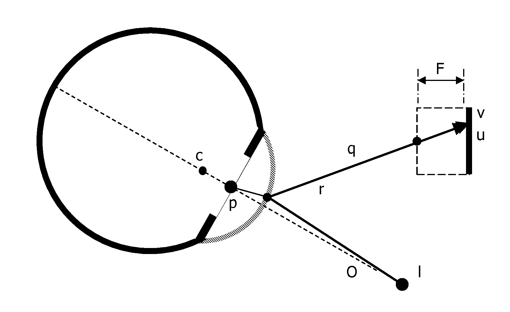
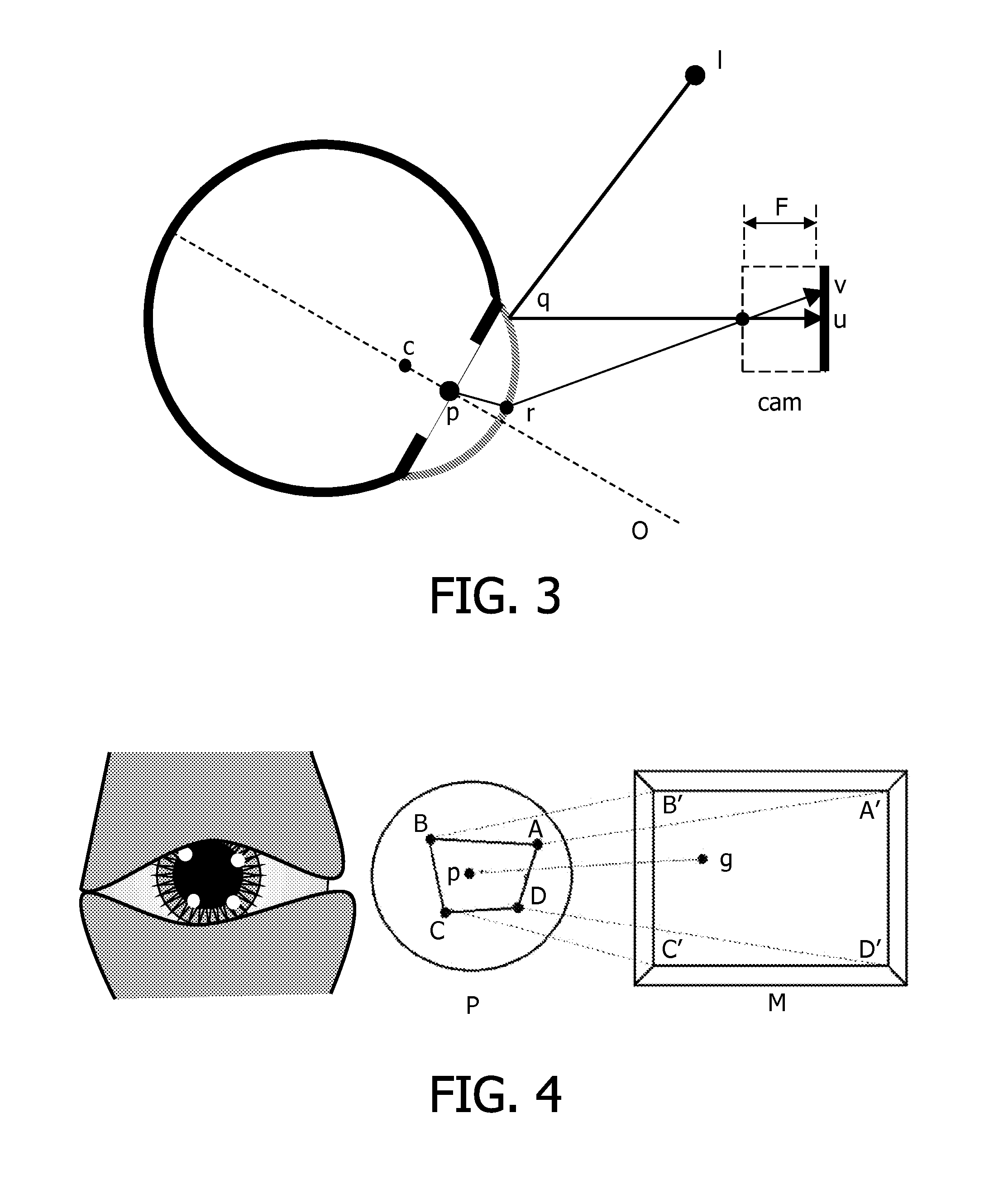
[0100]FIG. 10 illustrates an example of a system in accordance with the invention. A first embodiment is based on the use of an LCD display 102 which has an IR backlight (IR) in addition to the normal visible backlight (RGB) as depicted in FIG. 10. The implementation and control of the system, using control unit C is in principle similar to that of scanning-backlight LCD systems and particularly of colour-sequential LCD systems. The video camera (cam) is synchronised with the backlighting system. The synchronization causes the backlight to alternate between IR and visible light. During the visible-light phase the normal image is shown. During the IR phase the LCD panel 102 displays a pattern that serves as the movable IR marker 103; during this phase the camera (CAM) captures an image of the eye 101 with the reflected marker. The centre of the pupil can be obtained using the method discussed earlier, e.g. during the visible-light phase. Experiments have shown that LC material is cap...

second embodiment

[0102]IR-marker superposition is to use spatially segmented IR backlight in addition to the visible backlight. By choosing the IR light wavelength sufficient far from the visible range, it has been found that the LC material becomes transparent to the IR light, regardless the open or closed state of the pixels. The advantage is that the visible backlight can stay active and the LC panel can be used exclusively for the normal visible image. Now, the resolution of the IR marker is that of the segmented IR backlight. The segmented IR backlight is controlled to control the position of the IR marker. In this example the means to provide a marker are also integrated into the display means, but to a lesser degree than in the first example. Alternatively the means to provide a marker can be formed by a projector which projects an IR beam, via a system of movable mirrors on the LC display device. In this example the means to provide a marker are much more separated from the display device.

[0...


PUM


Abstract

A system for tracking the point of gaze of an observer observing an object comprises a camera for recording an image of an eye of the observer, comprises a means for providing a luminous marker, and means for analyzing the image of the eye to determine the reflection of the marker on the eye and the centre of the pupil. The relative positions of the corneal reflection of the marker and the pupil centre are measured. The marker is repositioned, in dependence on the determined relative positions, to improve correspondence between the corneal reflection of the marker and the pupil centre.

Description

FIELD OF THE INVENTION[0001]The invention relates to a system for tracking the point of gaze of an observer observing an object, wherein the system comprises a device for recording an image of an eye of the observer, comprises a means for providing a luminous marker on or associated with the observed object, and a means for determining from the image a corneal reflection of the marker and the centre of the pupil.[0002]The invention further relates to a method for tracking the point of gaze of an observer observing an object, wherein the method comprises recording an image of an eye of the observer, providing a luminous marker on or associated with the observed object, and determining from the image a corneal reflection of the marker and the centre of the pupil.BACKGROUND OF THE INVENTION[0003]A system and method of the above type is known from US patent application US 2006 / 0110008.[0004]In this document a number of markers are provided and at least one marker of which the corneal re...

Claims


Application Information

Patent Timeline
Patent Type & Authority Applications(United States)
IPC IPC(8): H04N7/18
CPCA61B3/113G06F3/013G06K9/0061G09G2380/12G06F3/147G06V40/193
Inventor DE BRUIJN, FREDERIK JANVAN BREE, KARL CATHARINAGRITTI, TOMMASO
Owner KONINKLIJKE PHILIPS ELECTRONICS NV
Why Eureka
Try Eureka