Display device and television receiver

a technology for television receivers and display panels, which is applied in the field of display devices and television receivers, can solve the problems of reducing brightness, yellowishness of display images, and yellowishness of output light from the display panel, and achieve excellent color reproducibility and high brightness

Inactive Publication Date: 2013-01-03
SHARP KK
View PDF4 Cites 14 Cited by
  • Summary
  • Abstract
  • Description
  • Claims
  • Application Information

AI Technical Summary

Benefits of technology

[0045]According to the present invention, both high brightness and excellent color reproducibility can be obtained.

Problems solved by technology

On the other hand, when the yellow color section is included in the color filter, the output light from the display panel, i.e., the display image, tends to have yellowishness as a whole.
However, this chromatic correction method tends to decrease in the amount of transmitted light, possibly resulting in a decrease in brightness.

Method used


Image

  • Display device and television receiver
  • Display device and television receiver
  • Display device and television receiver

Examples


first embodiment

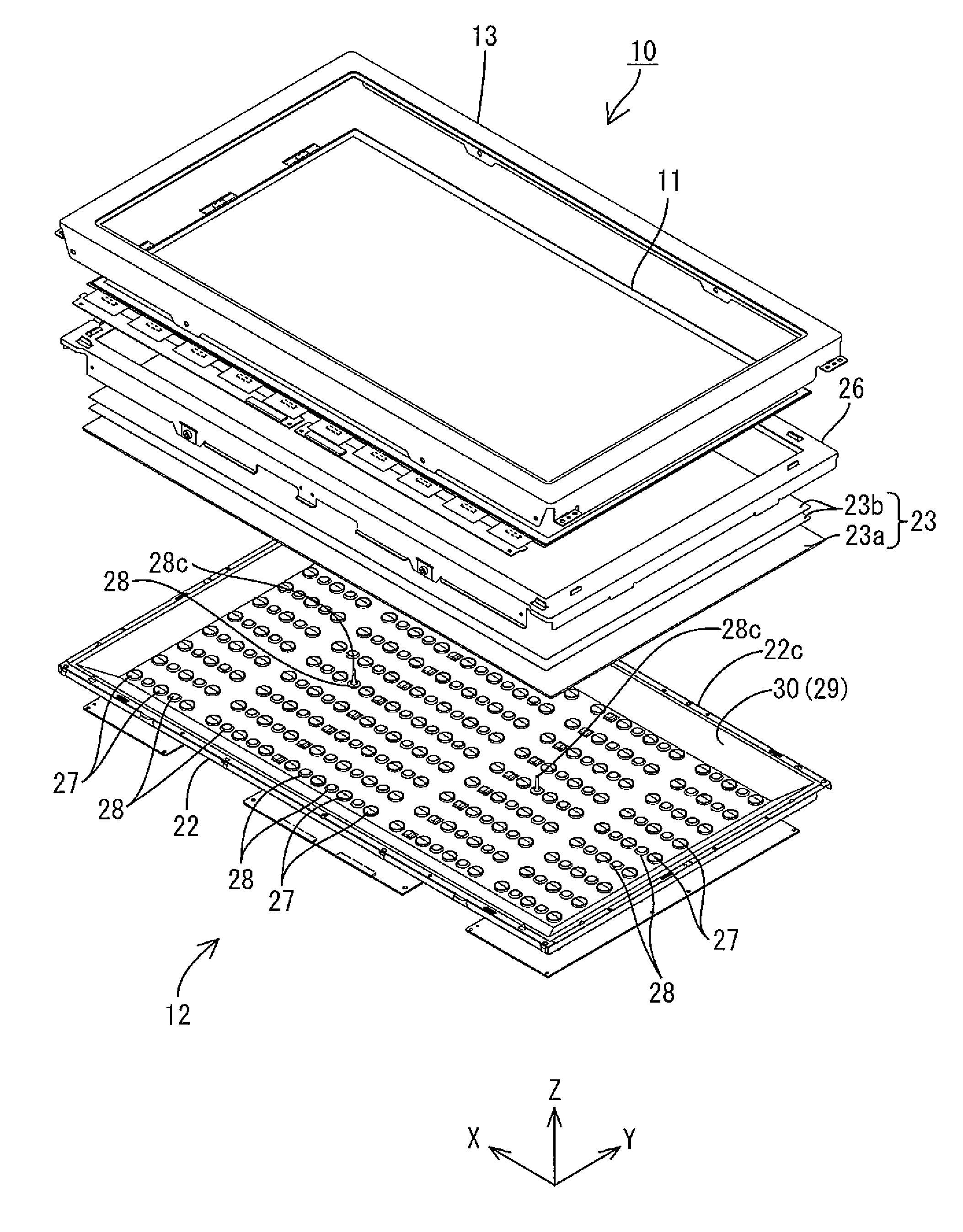
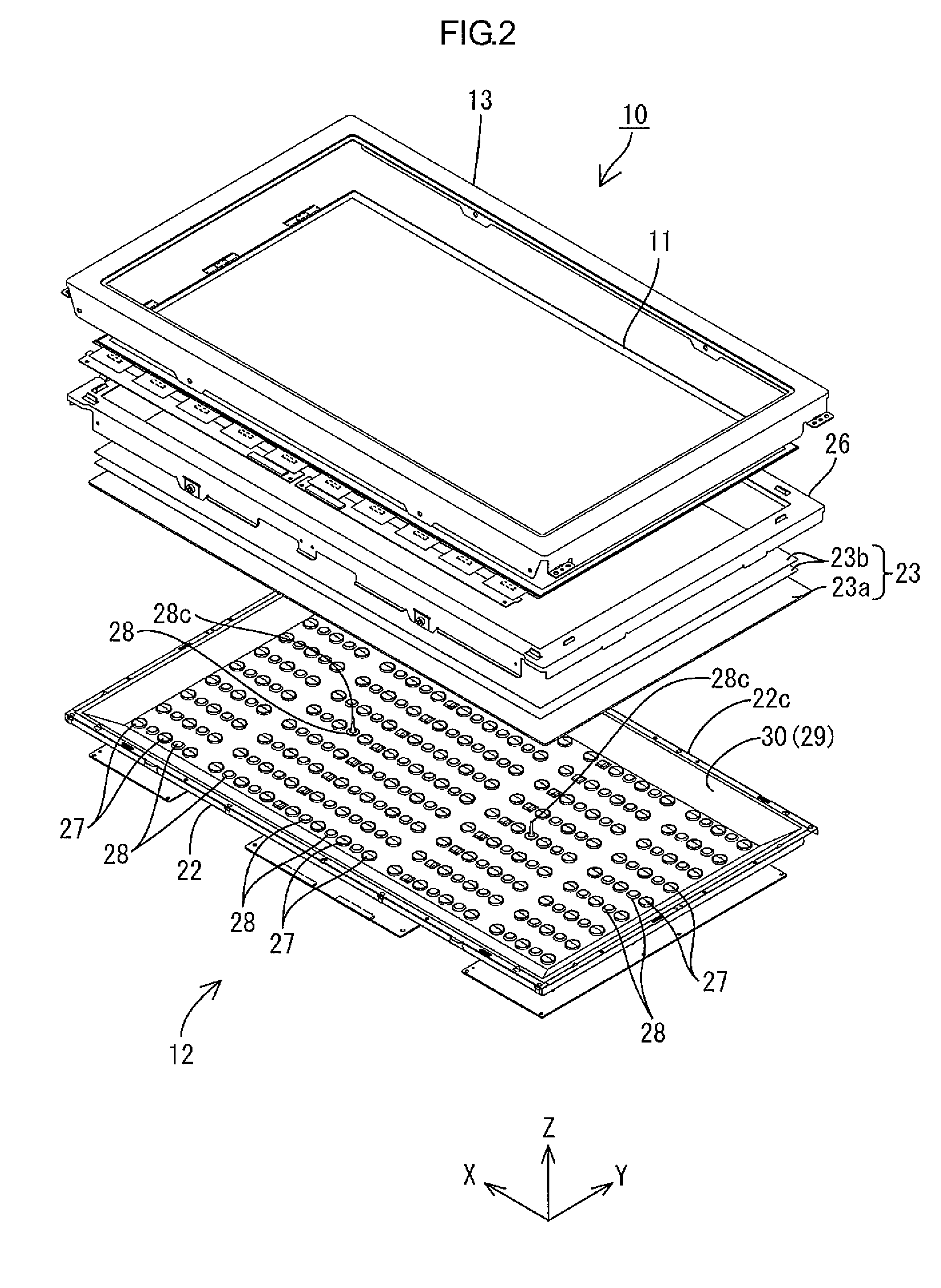
[0070]A first embodiment of the present invention will be described with reference to FIGS. 1 to 16. According to the present embodiment, a liquid crystal display device 10 will be described by way of example. In some parts of the drawings, an X-axis, a Y-axis, and a Z-axis are shown as the respective axial directions corresponding to the directions shown in the respective drawings. The upper side and the lower side shown in FIGS. 7 and 8 correspond to the front side and the rear side, respectively.

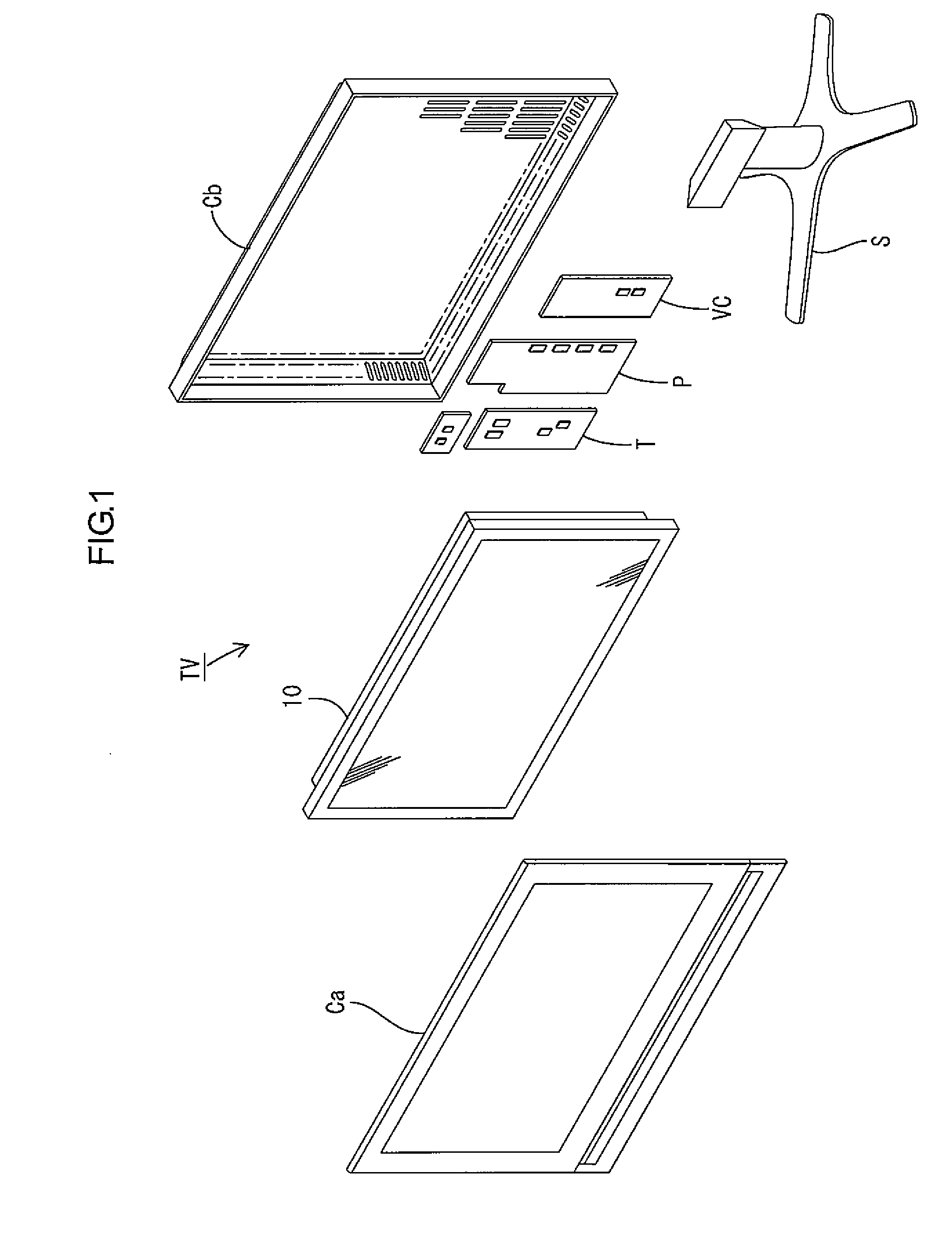
[0071]A television receiver TV according to the present embodiment, as shown in FIG. 1, includes the liquid crystal display device 10; front and rear cabinets Ca and Cb housing the liquid crystal display device 10 in a sandwiching manner; a power supply circuit board P supplying electric power; a tuner (reception unit) T configured to receive a television image signal; an image conversion circuit board VC converting the television image signal output from the tuner T into an image signal ...

second embodiment

[0151]A second embodiment of the present invention will be described with reference to FIGS. 17 to 20. The second embodiment differs from the first embodiment in that a backlight unit 212 of the edge light type is used. Redundant description of structures, operations, and effects similar to those of the first embodiment will be omitted.

[0152]A liquid crystal display device 210 according to the present embodiment, as shown in FIG. 17, includes a liquid crystal panel 211 and the edge light backlight unit 212 in an integrated manner using a bezel 213 or the like. The configuration of the liquid crystal panel 211 may be similar to the first embodiment and redundant description will be omitted. In the following, the configuration of the edge light backlight unit 212 will be described.

[0153]The backlight unit 212, as shown in FIG. 17, includes a substantially box-shaped chassis 222 with an opening on the light output surface side (the side facing the liquid crystal panel 211); and a group...

third embodiment

[0164]A third embodiment of the present invention will be described with reference to FIG. 21 or 22. The third embodiment differs from the second embodiment in the constituent components of a liquid crystal display device 110. Redundant description of structures, operations, or effects similar to those of the second embodiment will be omitted.

[0165]FIG. 21 is an exploded perspective view of the liquid crystal display device 110 according to the present embodiment. In FIG. 22, the upper side corresponds to the front side and the lower side corresponds to the rear side. As shown in FIG. 21, the liquid crystal display device 110 as a whole has a horizontally long square shape, and includes a liquid crystal panel 116 as a display panel and a backlight unit 124 as an external light source, which are configured to be integrally retained by a top bezel 112a, a bottom bezel 112b, side bezels 112c (hereafter referred to as a group of bezels 112a to 112c), and the like. The liquid crystal pan...


PUM

PropertyMeasurementUnit
emission wavelengthsaaaaaaaaaa
emission wavelengthaaaaaaaaaa

Abstract

It is an object of the present invention to obtain high brightness and high color reproducibility in a liquid crystal display device. A liquid crystal display device 10 according to the present invention includes a liquid crystal panel 11 and a backlight unit 12. The liquid crystal panel 11 includes a pair of substrates 11a and 11b, and a liquid crystal layer 11c. The liquid crystal layer 11C includes liquid crystal between the substrates 11a and 11b. The liquid crystal is a substance having optical characteristics that vary with application of an electric field. The backlight unit 12 includes a light source. The back light unit 12 is configured to irradiate light onto the liquid crystal panel 11. At least one of the substrates 11a and 11b of the liquid crystal panel 11 includes a color filter 19 with a plurality of color sections R, G, B, and Y that exhibit the colors of blue, green, red, and yellow, respectively. The backlight unit 12 includes LEDs 24 as the light source. Each LED 24 includes an LED element as a light emitting source and a phosphor configured to emit light when excited by the light from the LED element. The phosphor includes at least two types of phosphors with different dominant emission wavelengths in a range of 480 nm to 580 nm.

Description

TECHNICAL FIELD[0001]The present invention relates to a display device and a television receiver.BACKGROUND ART[0002]Generally, a liquid crystal panel as a main component of a liquid crystal display device includes a pair of glass substrates between which liquid crystal is sealed in. One of the glass substrates is an array substrate on which active elements, such as TFTs, are provided. The other substrate is a CF substrate on which a color filter and the like are provided. On an inner surface of the CF substrate opposed to the array substrate, a color filter including a plurality of color sections corresponding to the respective colors of red, green, or blue is formed. The color sections are arranged side by side correspondingly to the respective pixels of the array substrate. Between the color sections, a light blocking layer preventing mixing of the colors is provided. Light irradiated by a backlight and transmitted through the liquid crystal has its wavelength selectively transmi...

Claims


Application Information

Patent Timeline
Patent Type & Authority Applications(United States)
IPC IPC(8): G09F13/04G02F1/13357H04N5/44F21V8/00
CPCG02F1/133603G02F2202/046G02F2001/133614G02F1/133614
Inventor YOKOTA, MASASHI
Owner SHARP KK
Why Eureka
Try Eureka