Electronic Distance Measuring Method And Electronic Distance Measuring Instrument

Active Publication Date: 2013-01-03
KK TOPCON
View PDF2 Cites 17 Cited by
  • Summary
  • Abstract
  • Description
  • Claims
  • Application Information

AI Technical Summary

Benefits of technology

[0019]According to the present invention, an electronic distance measuring method comprises a step of performing coarse distance measurement based on difference of photodetection time between an internal reference pulsed light and a distance measuring pulsed light reflected from an object to be measured, a step of carrying out Fourier function transform on photodetection waveform of the internal reference pulsed light and photodetection waveform of the distance measuring pulsed light respectively, a step of separating the waveforms to a plurality of frequency components, a step of obtaining phase difference for each of the frequency components acquired, a step of performing fine distance measurement based on difference of time acquired from phase difference, and a step of measuring a distance to the object to be measured by adding a result of coarse distance measurement to a result of fine distance measurement. As a result, it is possible to perform approximate distance measurement easily by coarse measurement and to overcome the insufficiency of accuracy of the coarse measurement by precise (fine) measurement and to accomplish distance measurement with higher accuracy in easy and simple manner.
[0020]Further, according to the present invention, an electronic distance measuring instrument comprises a distance measuring optical path, an internal reference optical path, a pulsed light emitting light source for emitting a pulsed light, a pulsed light guiding means for directing the pulsed light emitted from the pulsed light source toward the distance measuring optical path as a distance measuring pulsed light and for directing the pulsed light toward the internal reference optical path as an internal reference pulsed light, a photodetector for emitting photodetection signal by detecting the distance measuring pulsed light and the internal reference pulsed light, and a measuring unit for calculating a distance to an object to be measured based on a photodetection signal from the photodetector, and in the electronic distance measuring instrument, the measuring unit performs coarse distance measurement based on difference of photodetection time between the internal reference pulsed light and the distance measuring pulsed light reflected from the object to be measured, carries out Fourier function transform on photodetection waveform of the internal reference pulsed light outputted by the photodetector and photodetection waveform of the distance measuring pulsed light respectively, separates the waveforms to a plurality of frequency components, obtains phase difference for each of the frequency components acquired, performs fine distance measurement based on time difference acquired from phase difference, and measures a distance to the object to be measured by adding a result of coarse distance measurement to a result of fine distance measurement. As a result, it is possible to perform approximat

Problems solved by technology

In the conventional type direct sampling systems, there have been such problems that these direct sampling systems are inferior to the systems for distance measurement using filter array because due to restriction of performance characteristics of sampling in A/D conversion, performance characteristics are in

Method used


Image

  • Electronic Distance Measuring Method And Electronic Distance Measuring Instrument
  • Electronic Distance Measuring Method And Electronic Distance Measuring Instrument
  • Electronic Distance Measuring Method And Electronic Distance Measuring Instrument

Examples


first embodiment

[0063]FIG. 3 is a block diagram to show the measuring unit 4 in the present invention. In FIG. 4, the measuring unit 4 comprises a trans-impedance amplifier used as an amplifier 15, an A / D converter 16, a data capture unit 17, a ring buffer unit 18, a digital comparator 19, a storage unit 20, a Fourier function transform unit (hereinafter referred as “FFT unit”) 21, a clock oscillator 24, a rough clock counter 25, a rough clock storage unit 26, an arithmetic control unit 27 for calculating a distance to the object to be measured, or the like.

[0064]A photodetection signal from the photodetector 6 is inputted to the amplifier 15, and a clock signal from the clock oscillator 24 is inputted to the light source driving unit 7 as a synchronization signal and a light emission instruction signal.

[0065]Each time an optical pulse is emitted, the measuring unit 4 carries out signal processing as described below on the photodetection signal of the reflected pulsed light and the internal referen...

second embodiment

[0101]FIG. 10 shows a measuring unit 4 in a In FIG. 10, the same component as shown in FIG. 3 is referred by the same symbol, and detailed description is not given here.

[0102]The second embodiment shows how correction is made in case the characteristics are changed according to temperature in an A / D converter 16.

[0103]A temperature sensor 31 for detecting temperature of the A / D converter 16 is provided, and an arithmetic control unit 27 has calibration data 32 for correcting the characteristics of the A / D converter 16.

[0104]The A / D converter 16, which is operated at high speed, has a multiple of cores for the A / D conversion inside, and the A / D converter 16 is operated at high speed by carrying out the A / D conversion by using these multiple of cores. However, these cores are slightly different from each other in the characteristics. To utilize performance characteristics of the A / D converter 16 to the full extent, it is necessary to correct the properties of these multiple of cores....

third embodiment

[0116]FIG. 11 shows a

[0117]In the third embodiment, compared with the first embodiment, an optical path splitting unit 34 is provided in place of an optical path changeover unit 11. Further, a distance measuring optical path extension 35 is disposed along a distance measuring optical path 13.

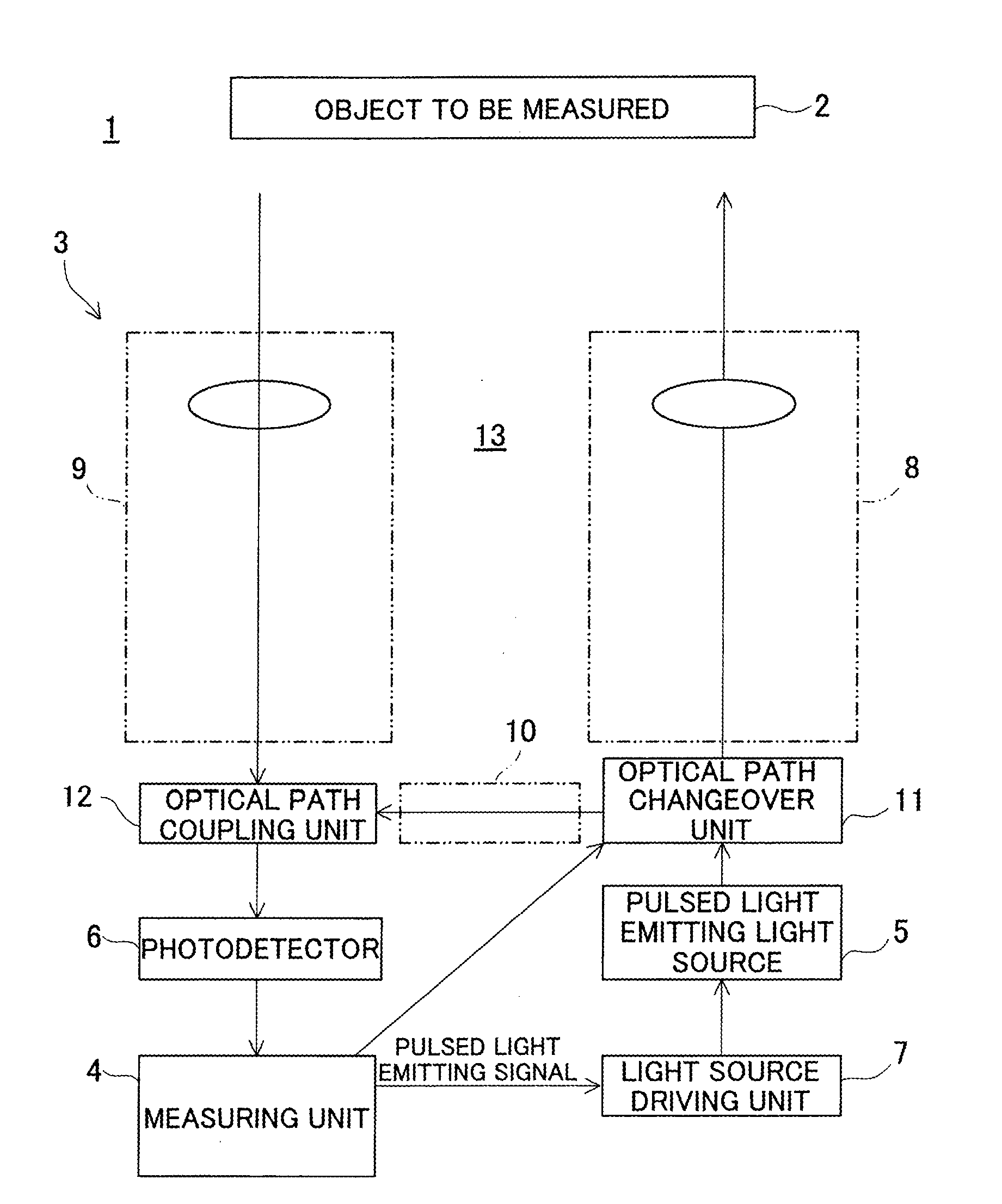
[0118]Optical fiber or the like may be used as the distance measuring optical path extension 35. The optical path splitting unit 34 fulfills the function as pulsed light guiding means which directs a pulsed light emitted from a pulsed light emitting light source 5 along the distance measuring optical path 13 and directs the pulsed light along an internal reference optical path 10 as an internal reference pulsed light.

[0119]In the third embodiment, one pulsed light is split to a distance measuring pulsed light and to an internal reference pulsed light by the optical path splitting unit 34.

[0120]The distance measuring optical path extension 35 delays reaching time of a reflected pulsed light to a ...


PUM


Abstract

An electronic distance measuring instrument comprises a pulsed light emitting light source, means for creating a distance measuring pulsed light and an internal reference pulsed light, a photodetector for detecting the pulsed lights, and a measuring unit for calculating a distance to an object to be measured based on a photodetection signal. The measuring unit performs coarse distance measurement based on difference of photodetection time between the internal reference pulsed light and the distance measuring pulsed light, carries out Fourier function transform on photodetection waveform of the pulsed lights respectively, separates the waveforms to a plurality of frequency components, obtains phase difference for each of the frequency components acquired, performs fine distance measurement based on time difference acquired from phase difference, and measures a distance to the object by adding a result of coarse distance measurement to a result of fine distance measurement.

Description

BACKGROUND OF THE INVENTION[0001]The present invention relates to an electronic distance measuring method and an electronic distance measuring instrument for projecting a pulsed light, for receiving a reflected pulsed light reflected from an object to be measured, and for measuring a distance to the object to be measured according to time difference from the time to project the pulsed light to the time to receive the reflected pulsed light.[0002]In the past, there have been thought up various types of electronic distance measuring instrument using the pulsed light, and a direct sampling system for converting waveform of the pulsed light directly by analog-digital conversion has also been used.[0003]In the conventional type direct sampling systems, there have been such problems that these direct sampling systems are inferior to the systems for distance measurement using filter array because due to restriction of performance characteristics of sampling in A / D conversion, performance c...

Claims


Application Information

Patent Timeline
IPC IPC(8): G01C3/08G01S7/4865G01S17/10
CPCG01S7/4865G01S17/10G01S7/497
Inventor YOSHINO, KEN-ICHIROKUMAGAI, KAORUKANOKOGI, MITSURUMATSUMOTO, MASAE
Owner KK TOPCON
Why Eureka
Try Eureka