
Reentry Catheter and Method Thereof

a technology of reentry catheter and tubular member, which is applied in the field of reentry catheter, can solve the problems of reducing the overall required size of the device, reducing the probability of limb amputation, and restricting normal blood flow, so as to improve the stability and control of the distal tip. , the effect of reducing the force required

Active Publication Date: 2013-01-03
SPECTRANETICS
View PDF2 Cites 32 Cited by
  • Summary
  • Abstract
  • Description
  • Claims
  • Application Information

AI Technical Summary

Benefits of technology

The invention provides a device that can be easily moved through narrowed blood vessels and used to treat blockages. The device has a flexible cannula or sharp member that reduces the force needed to reenter the main vessel, and a long rigid element is not needed at the tip to support large reentry forces, which makes the device smaller and more stable. The device is also designed to improve stability and control during deployment, preventing it from backing out or separating from the blood vessel wall. Additionally, the device is designed to improve trackability and control, allowing a physician to access the true vessel lumen at a preferred location close to the distal end of the blockage.

Problems solved by technology

These deposits accumulate in localized areas, narrow the vascular lumen, and eventually causing restriction of normal blood flow.
Such restriction can lead to a serious health risk including critical limb ischaemia.
If blood flow cannot be adequately restored through surgical or endovascular intervention and the probability of limb amputation increases dramatically.
Until recently, chronic total occlusions have been treated by bypass which poses high procedural risks and is quite traumatic to the patient.
In many instances, the physician encounters a calcified cap on the proximal end of the occlusion and is unable to maneuver the guide wire through the cap and across a calcified or fibrous lesion.
Once in the subintimal space, it is difficult to direct the guide wire back into the vessel lumen making it nearly impossible to perform a catheter based intravascular procedure.
This is a highly skilled technique with a low to moderate success level of consistent re-entry at the physician's preferred location just distal to the occlusion.
One problem with these methods is a tendency of the catheter to back out as a result of the moment imposed by force required to penetrate the subintimal layers to gain access to the vessel true lumen.
This is particularly problematic in the presence of calcified lesions causing an increase in the forces necessary for successful re-entry and, in many cases, requiring the physician to re-enter at a sub-optimal location.

Method used


Image

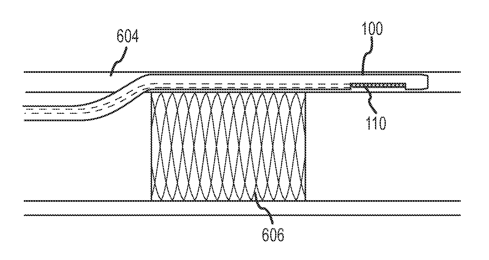
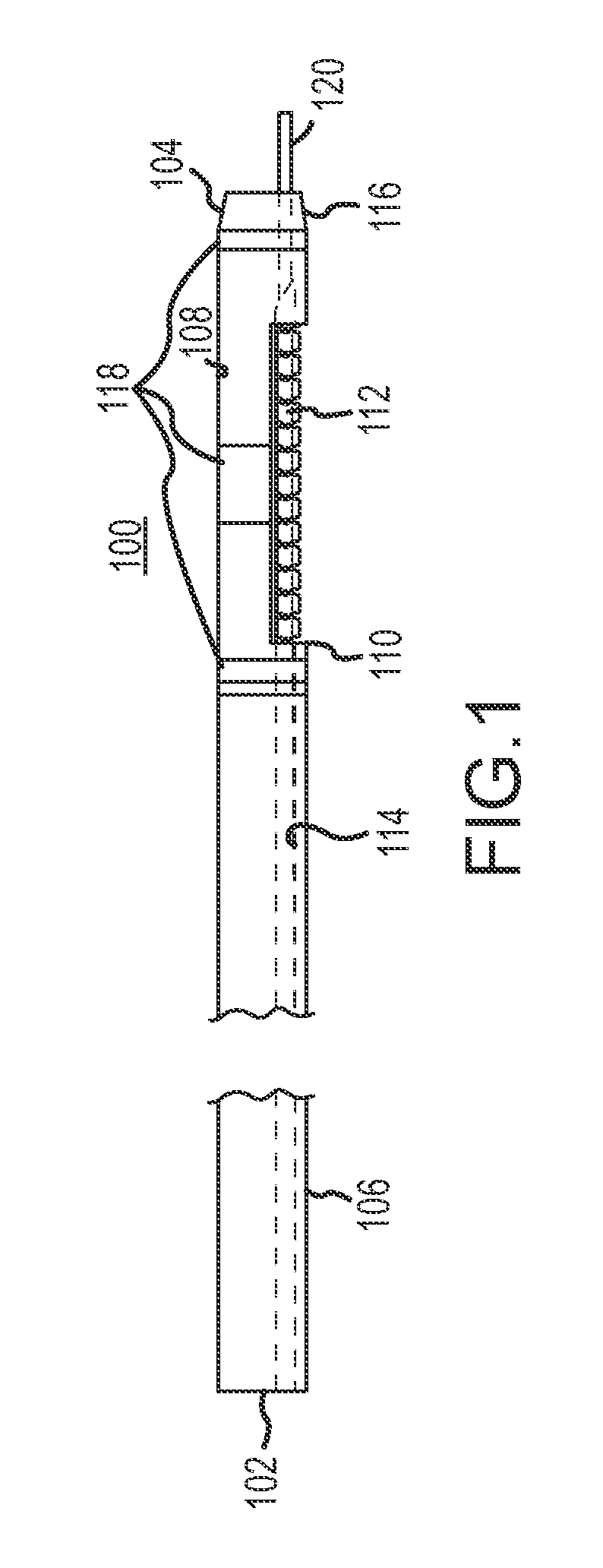
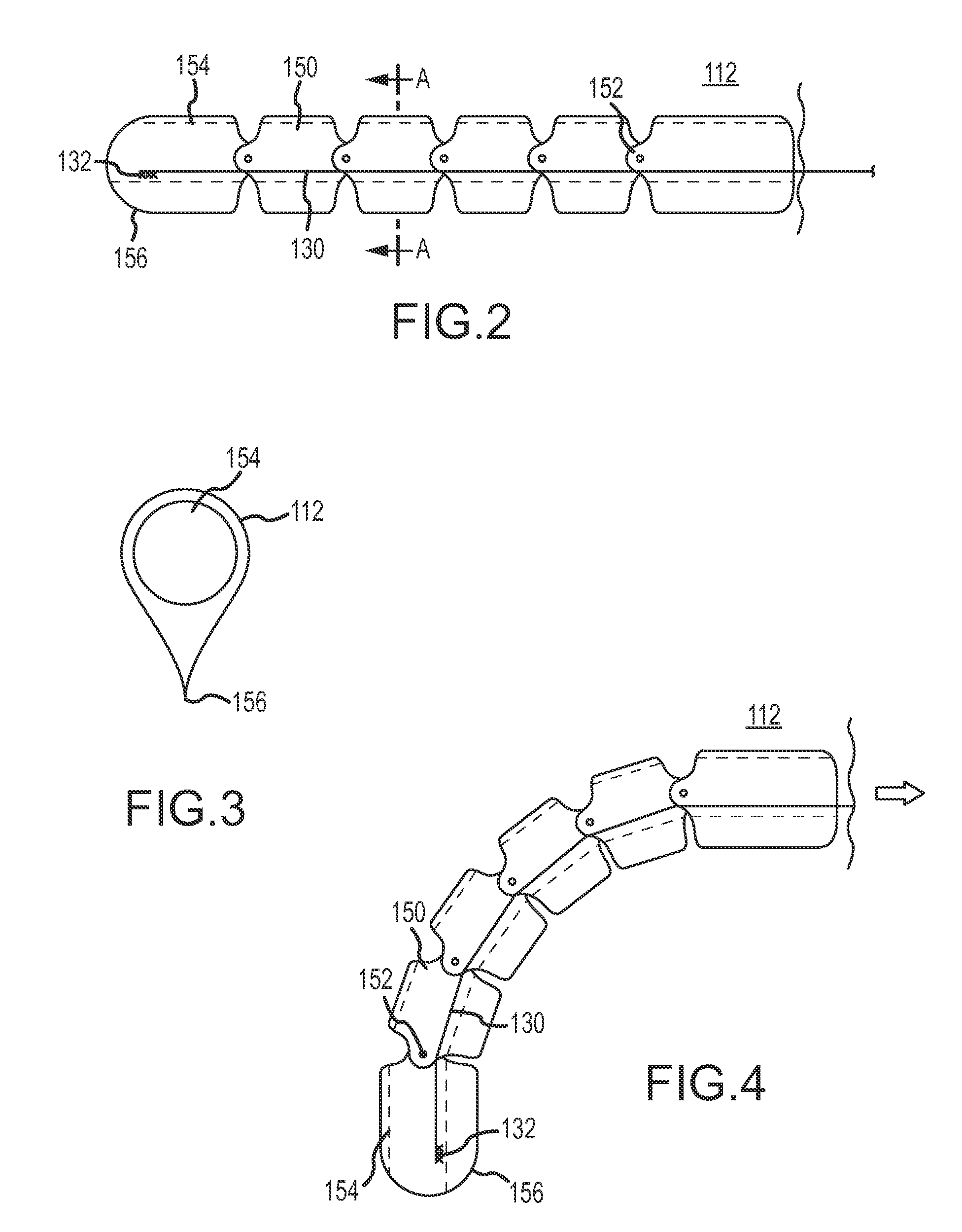
  • Reentry Catheter and Method Thereof
  • Reentry Catheter and Method Thereof
  • Reentry Catheter and Method Thereof

Examples


Embodiment Construction

[0029]The invention generally relates to a method and system for crossing an obstruction in a tubular member, e.g., crossing a chronic total occlusions in a blood vessel, and more particularly to a medical device method for crossing of an occlusion in a subintimal or interstitial space of an artery. Subintimal or interstitial region or space is at a location beneath at least a portion of intima and preferably at a location contained between the intima and the adventitia of the vessel. The terms tubular member, artery, vessel and bodily passable are used interchangeably throughout the specification.

[0030]An embodiment of the invention is directed towards a catheter for insertion into a subintimal space. The catheter includes a proximal end, a distal end, at least one lateral port, and at least one lumen. The at least one lumen extends longitudinally through the lateral port of the catheter. The catheter may also include an exchange port, e.g., RX port, arranged along an exterior port...


PUM


Abstract

The invention generally relates to method and apparatus for crossing an obstruction in a tubular member, and more particularly to a medical device method for crossing of a chronic occlusion in a subintimal or interstitial space of an artery.

Description

CROSS-REFERENCE TO RELATED APPLICATIONS[0001]This application claims the benefit of U.S. Provisional Patent Application No. 61 / 503,477, filed on Jun. 30, 2011, which is hereby incorporated by reference for all purposes as if fully set forth herein.FIELD OF THE INVENTION[0002]The invention generally relates to method and apparatus for crossing an obstruction in a tubular member, and more particularly to a medical device method for crossing a chronic occlusion in a subintimal or interstitial space of an artery.BACKGROUND OF THE INVENTION[0003]Atherosclerosis is a common human ailment arising from deposition of fatty-like substance, such as atheroma, or plaque on the walls of major blood vessels. These deposits occur within the peripheral arterial system which feeds the limbs of the body and also occur within the coronary arterial system which feeds the heart. These deposits accumulate in localized areas, narrow the vascular lumen, and eventually causing restriction of normal blood flo...

Claims


Application Information

Patent Timeline
IPC IPC(8): A61M25/09A61M25/092A61M25/10A61M25/00A61M25/098
CPCA61M25/0138A61M25/0194A61M2025/0197A61M2025/0183A61M2025/0096A61B17/3207A61B2017/320056A61M2205/32
Inventor ALVAREZ, JEFFERY B.NEVRLA, DAVID S.
Owner SPECTRANETICS
Learn More