Welding tip replacement apparatus, welding tip replacement system, and method for replacing welding tip

a welding tip and welding tip technology, applied in the field of apparatus, system and method for replacing welding tips, can solve the problems of poor current supply to wire, wear of relevant parts, and manual replacement of welding tips that require time and effort, and achieves simple structure, convenient removal and attachment, and reduce the number of processing steps.

Inactive Publication Date: 2013-01-10
KOBE STEEL LTD
View PDF1 Cites 22 Cited by
  • Summary
  • Abstract
  • Description
  • Claims
  • Application Information

AI Technical Summary

Benefits of technology

[0033]The detaching and attaching steps of the welding tip replacing method involve displacing the retaining member axially and displacing the welding tip (or the welding torch) axially. It is unnecessary to rotate the welding tip. The welding tip replacing method therefore enables welding tips to be easily detached and attached.
[0034]This welding tip replacing method allows the use of a welding tip replacement apparatus having the above-described simple structure in which a rotator for replacing a welding tip and a mechanism for applying a large torque to the rotator are omitted.
[0035]The welding tip replacement apparatus according to any of the aspects of the present invention does not require a rotator, which is essential to a related-art welding tip replacement apparatus, for replacement of a welding tip, and accordingly does not require a mechanism for applying a large torque to the rotator. According to the present invention, therefore, the welding tip replacement apparatus with a simple structure can be provided.
[0036]Furthermore, in the welding tip replacement apparatus according to any of the aspects of the present invention, it is unnecessary to apply external forces to the retaining member in directions other than the direction along the axis in order to detach or attach the welding tip. For example, while a cylindrical nozzle covering the outer curved surface of the retaining member remains attached to the welding torch, a welding tip can be detached or attached. The welding tip replacement apparatus according to any of the aspects of the present invention can therefore reduce the number of processing steps necessary for detachment and attachment of welding tips, thus reducing operation time.

Problems solved by technology

During gas shielded arc welding, the wire rubs against the inner surface of the through-hole at the distal end of the welding tip, so that relevant portions become worn.
Accordingly, the inside diameter of the through-hole is increased, thus shifting a welding position or causing poor current supply to the wire.
Manual replacement of welding tips requires time and effort, which may significantly reduce the availability of the welding facility.
Accordingly, such a welding tip replacement apparatus has to have a complicated structure.

Method used


Image

  • Welding tip replacement apparatus, welding tip replacement system, and method for replacing welding tip
  • Welding tip replacement apparatus, welding tip replacement system, and method for replacing welding tip
  • Welding tip replacement apparatus, welding tip replacement system, and method for replacing welding tip

Examples


first embodiment

Welding Tip Replacement Apparatus (First Embodiment)

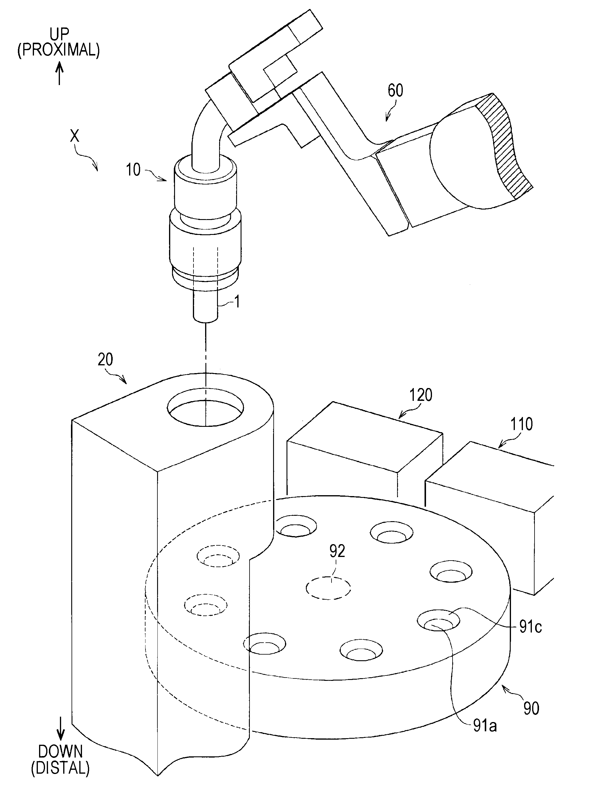
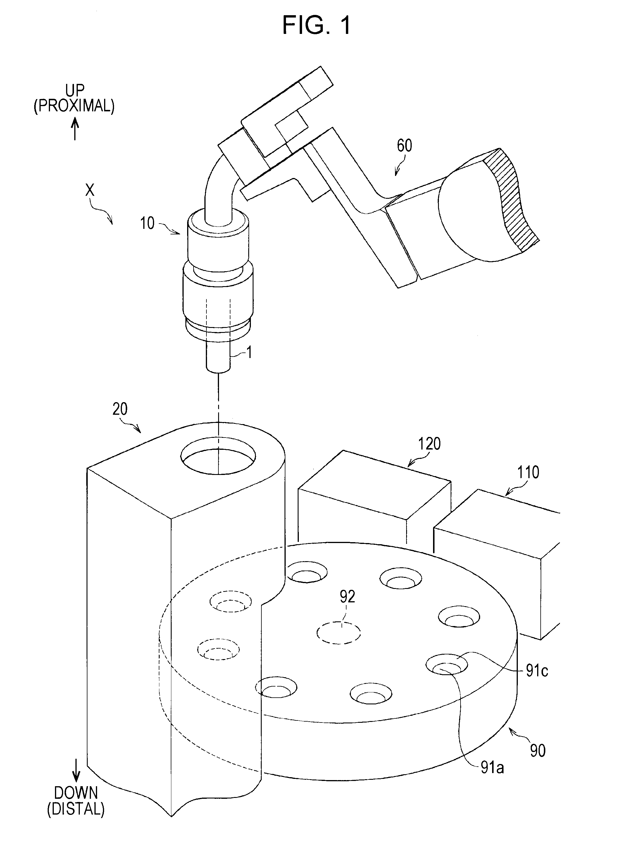
[0088]The welding tip replacement apparatus 20 according to the first embodiment is configured to detach the welding tip 1, which has to be replaced, from the welding torch 10 and attach another welding tip 11 (hereinafter, appropriately referred to as a “new welding tip 11”) placed on a pallet.

[0089]Referring to FIG. 3A, the welding tip replacement apparatus 20 according to the first embodiment includes a first grasping mechanism 21 for grasping the retaining member 4 of the welding torch 10, a second grasping mechanism 23, located under the first grasping mechanism 21, for grasping the welding tip 1, a first driving mechanism 22, coupled to the first grasping mechanism 21, for moving the first grasping mechanism 21 in up and down directions, and a second driving mechanism 24, coupled to the second grasping mechanism 23, for moving the second grasping mechanism 23 in the up and down directions.

[0090]The welding tip replacement app...

second embodiment

Controller (Second Embodiment)

[0169]The controller 70 according to the second embodiment has a configuration similar to that of the controller 70 according to the first embodiment as illustrated in FIG. 12, except for data indicating a driving sequence (progress schedule) for the devices stored in the memory unit 73 and signals output from the replacement apparatus control means 71a.

[0170]The replacement apparatus control means 71a is configured to output a signal for controlling driving of the pressing member 31 along its axis, i.e., a signal indicating to which of the first position (FIGS. 10A to 10C) where the pressing member 31 is positioned in the highest level, the second position (FIGS. 11A and 11B) where the member is positioned lower than the first position, and the third position (FIGS. 11C and 11D) where the member is positioned at the lowest level the pressing driving mechanism 33 drives the pressing member 31.

Pallet

[0171]Referring to FIG. 10A, the pallet 100 used in th...


PUM

PropertyMeasurementUnit
angleaaaaaaaaaa
angleaaaaaaaaaa
currentaaaaaaaaaa

Abstract

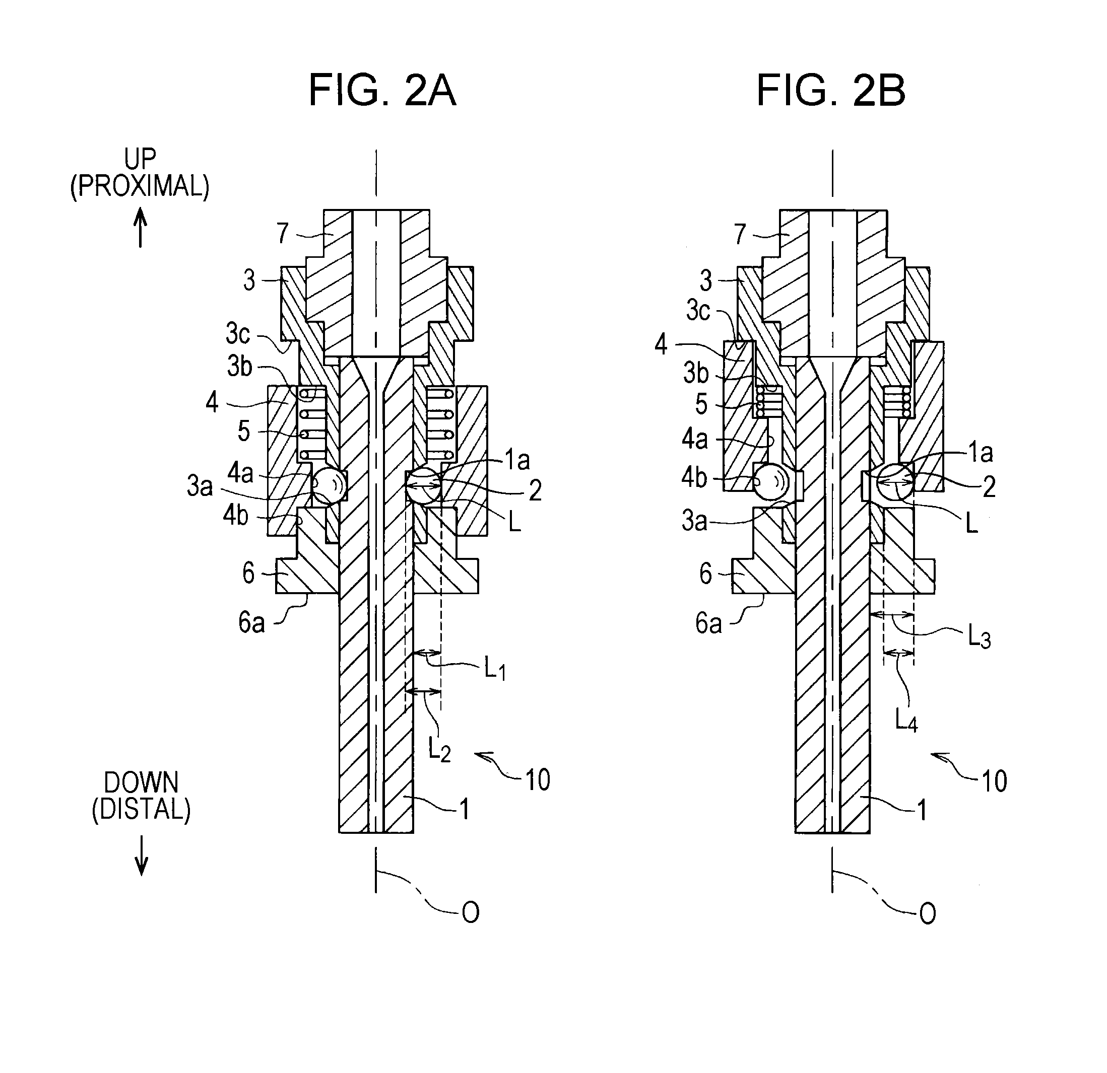
A welding tip replacement apparatus is used for a welding torch that includes a tubular tip connection body, a tubular retaining member fitted over the tip connection body, and a tubular welding tip fitted within the tip connection body, the welding torch being configured such that displacing the retaining member toward the proximal end of the tip connection body along the axis of the tip connection body causes the welding tip axially fastened to the tip connection body to be released. The apparatus includes a first grasping mechanism grasping the retaining member, a second grasping mechanism grasping the welding tip protruding from the retaining member in a direction away from the distal end of the tip connection body, a first driving mechanism driving the first grasping mechanism axially, and a second driving mechanism driving the second grasping mechanism axially.

Description

BACKGROUND OF THE INVENTION[0001]1. Field of the Invention[0002]The present invention relates an apparatus, system, and method for replacing a welding tip used for gas shielded arc welding.[0003]2. Description of the Related Art[0004]In gas shielded arc welding, a disposable copper electrode called a contact tip (hereinafter, referred to as a “welding tip”) is typically used as a member for supplying current to a wire. The welding tip has a through-hole. The wire is continuously fed to the through-hole and current is supplied to the wire through the welding tip, thus generating an electric arc between the wire protruding from the distal end of the welding tip and a base material.[0005]During gas shielded arc welding, the wire rubs against the inner surface of the through-hole at the distal end of the welding tip, so that relevant portions become worn. Accordingly, the inside diameter of the through-hole is increased, thus shifting a welding position or causing poor current supply to...

Claims


Application Information

Patent Timeline
Patent Type & Authority Applications(United States)
IPC IPC(8): B23P6/00
CPCB23K9/26B23K9/32B25J15/0416Y10S483/902Y10T483/17Y10T29/53Y10T29/4973B25J15/0491B23K9/12B23K9/16
Inventor IZUTANI, SHUNSUZUKI, REIICHI
Owner KOBE STEEL LTD
Why Eureka
Try Eureka