Circuits for sensing current levels within a lighting apparatus incorporating a voltage converter

a voltage converter and circuit technology, applied in the field of circuits for sensing current levels within lighting apparatuses, can solve the problems of reducing the overall energy efficiency of the light fixture, reducing the energy efficiency of the leds and therefore the overall light fixture, and reducing the resistance of the current sense circuit.

Active Publication Date: 2013-01-10
ARKALUMEN
View PDF8 Cites 78 Cited by
  • Summary
  • Abstract
  • Description
  • Claims
  • Application Information

AI Technical Summary

Benefits of technology

[0010]In an embodiment of the invention there is provided a circuit comprising: a voltage converter operable to receive an input voltage and generate an output voltage defined between a high voltage rail and a low voltage rail coupled to the output of the voltage converter; a current sense circuit coupled to the voltage converter at a node to receive a sense current, the current sense circuit comprising...

Problems solved by technology

For instance, inefficiencies within the optics used and the AC/DC power supply both reduce the overall energy efficiency for the light fixture.
Further, operating the LEDs at non-optimal current (amperage) levels can reduce the energy efficiency of the LEDs and therefore the overall light fixture.
In fact, if the current flowing through the LEDs exceeds a maximum allowable level, the LEDs may be damaged or permanently burnt out, and thus require replacement.
One issue that arises when managing the current flow through the LEDs is that LEDs are not constant in terms of their forward voltages (voltage drops), or other characteristics such ...

Method used


Image

  • Circuits for sensing current levels within a lighting apparatus incorporating a voltage converter
  • Circuits for sensing current levels within a lighting apparatus incorporating a voltage converter
  • Circuits for sensing current levels within a lighting apparatus incorporating a voltage converter

Examples


Embodiment Construction

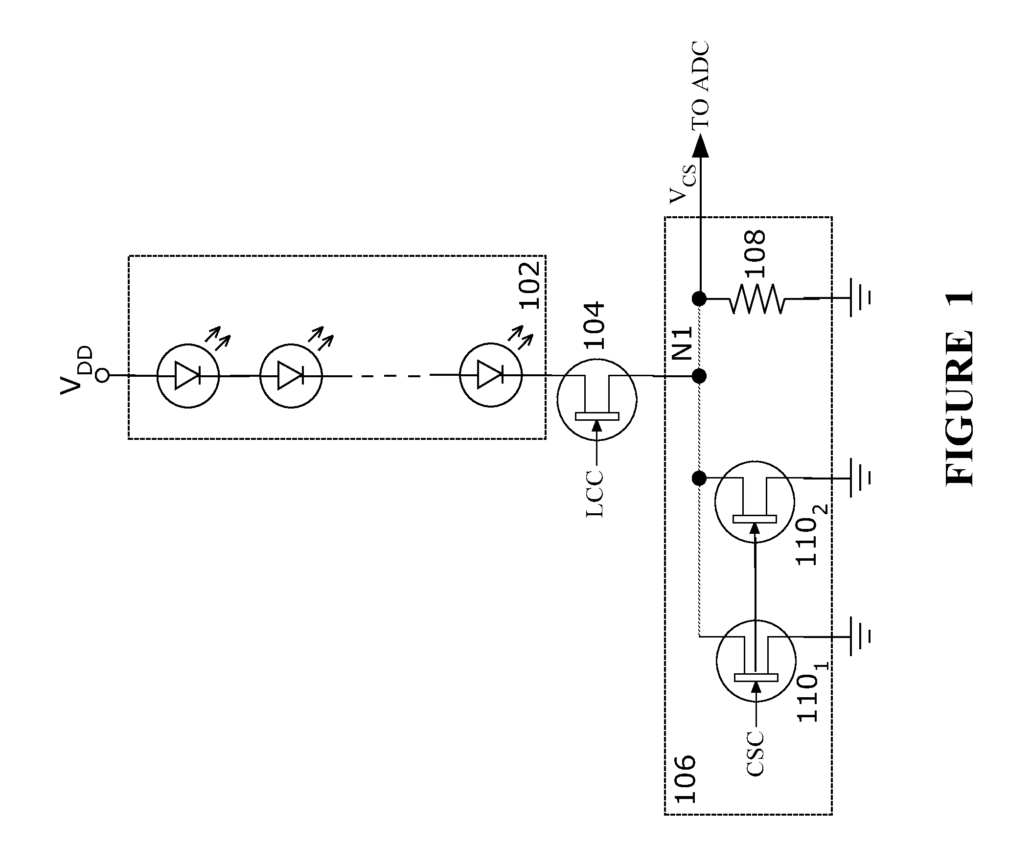
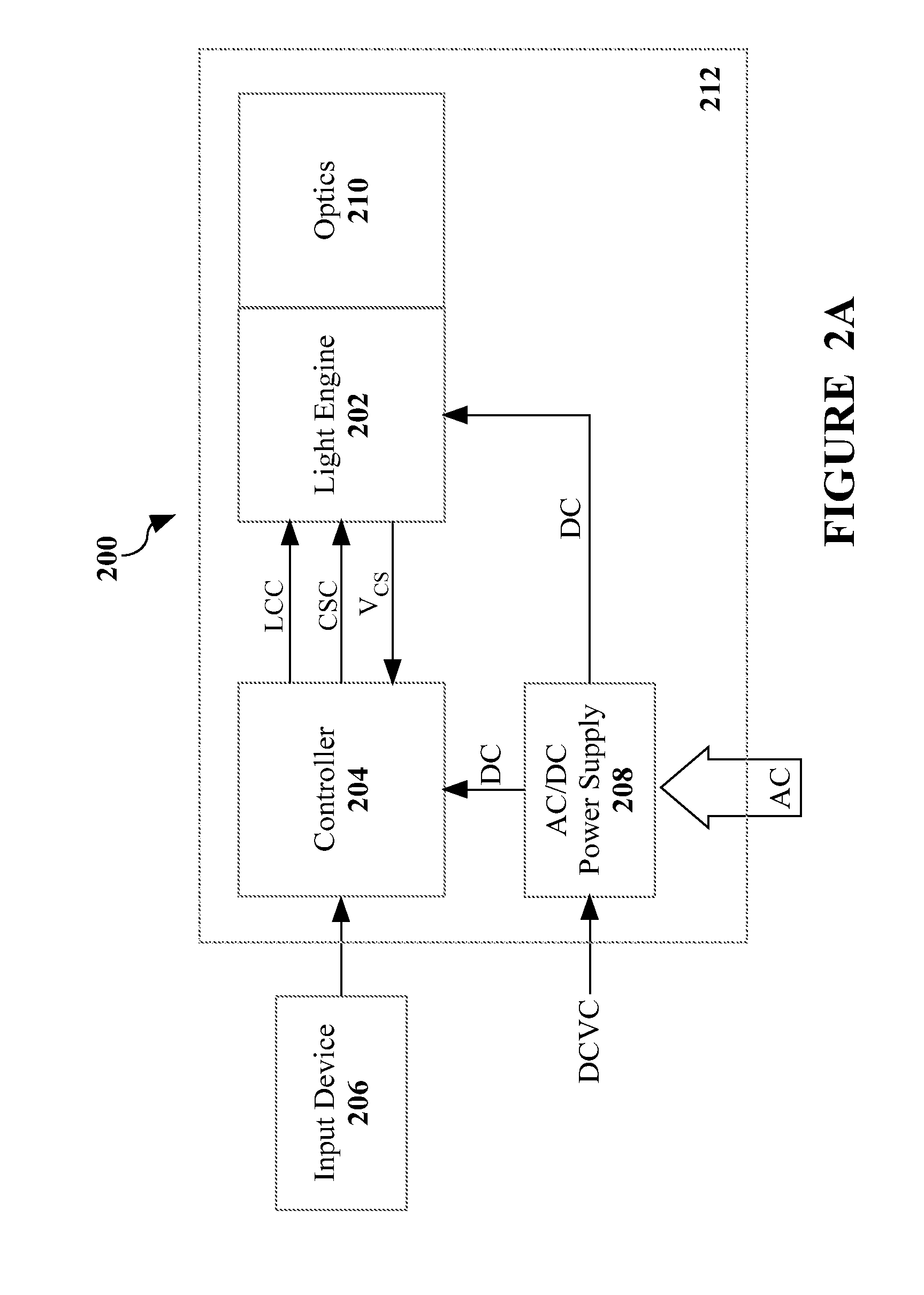
[0025]The present invention is directed to circuits for sensing current levels within apparatus. In embodiments of the present invention, a constant voltage power supply is used to power an LED lighting apparatus in which there are uncertainties within the forward voltages of the LEDs, which in turn creates uncertainty with respect to the current level flowing through the LEDs. To manage these uncertainties, the current flowing through the LEDs is measured by determining a voltage level across a known resistor and calculating the current level. To prevent the known resistor from causing a significant reduction in the efficiency of the overall light engine, the circuit includes one or more transistors in parallel with the known resistor to reduce the effective resistance in the LED circuit during times that the current is not being sensed.

[0026]FIG. 1 is an electrical circuit diagram of a light engine according to one embodiment of the present invention. As shown, the circuit of FIG....


PUM


Abstract

Circuits for sensing current levels within an apparatus are disclosed. In specific cases, a constant voltage power supply is used to power an LED lighting apparatus in which there are uncertainties within the forward voltages of the LEDs, which in turn creates uncertainty with respect to the current level flowing through the LEDs. To manage these uncertainties, the current flowing through the LEDs is measured by determining a voltage level across a known resistor and calculating the current level. To prevent the known resistor from causing a significant reduction in the efficiency of the overall light engine, the circuit includes one or more transistors in parallel with the known resistor to reduce the effective resistance in the LED circuit during times that the current is not being sensed.

Description

CROSS-REFERENCE TO RELATED APPLICATION[0001]The present application is a continuation in part of and claims the benefit under 35 USC 120 of U.S. patent application Ser. No. 13 / 104,919 entitled “Circuits for Sensing Current Levels Within Lighting Apparatus” by Briggs filed on May 10, 2011 and U.S. patent application Ser. No. 13 / 104,926 entitled “Methods and Apparatus for Changing a DC Supply Voltage Applied to a Lighting Circuit” by Briggs filed on May 10, 2011, both of which are hereby incorporated by reference. The present application further claims the benefit under 35 USC 119(e) of U.S. Provisional Patent Application No. 61 / 507,117 entitled “Dimmable LED Lighting Architecture Incorporating a Voltage Converter” by Briggs filed on Jul. 12, 2011 and hereby incorporated by reference.FIELD OF THE INVENTION[0002]The invention relates generally to lighting apparatus and, more particularly, to circuits for sensing current levels within lighting apparatus.BACKGROUND[0003]Light Emitting Di...

Claims


Application Information

Patent Timeline
IPC IPC(8): H05B37/02H05B44/00
CPCG01R1/203H05B33/0851G01R19/0092H05B45/46H05B45/10H05B47/10H05B45/14H05B45/48
Inventor BRIGGS, GERALD EDWARD
Owner ARKALUMEN
Why Eureka
Try Eureka