
Direct power and stator flux vector control of a generator for wind energy conversion system

a technology of wind energy conversion system and generator, applied in the direction of direct torque control, control system, electrical apparatus, etc., can solve the problems of only valid generator models, reducing power conversion efficiency, and affecting the efficiency of power conversion, so as to facilitate the determination of the switching times of the switches on the converter, the effect of easy and efficient control

Active Publication Date: 2013-01-10
VESTAS WIND SYST AS
View PDF1 Cites 14 Cited by
  • Summary
  • Abstract
  • Description
  • Claims
  • Application Information

AI Technical Summary

Benefits of technology

The objective of this patent is to provide a better way to control the stator current in a generator. The method and device described here make it easier and more efficient to switch the stator current using a vector that represents the difference in the stator flux. This helps to determine when to switch the switches on the converter. Overall, this technology makes it possible to better manage and control the production of electricity.

Problems solved by technology

This fact result in that any imbalance in the three phase system or any interaction between the phases will not be considered in this type of control.
Moreover, it is evident that the generator model will only be valid during steady state operation of the generator.
This result in a decreased power conversion efficiency as well as a need to oversize the electrical components of the WTG system in order to cope with transient surge currents and voltages.
This may put the controller reliability into stress under extreme conditions of load.
Case (b) on the other hand relates to under utilization of the DC-link voltage due to lack of faithful control at higher modulation indexes.

Method used


Image

  • Direct power and stator flux vector control of a generator for wind energy conversion system
  • Direct power and stator flux vector control of a generator for wind energy conversion system
  • Direct power and stator flux vector control of a generator for wind energy conversion system

Examples


Embodiment Construction

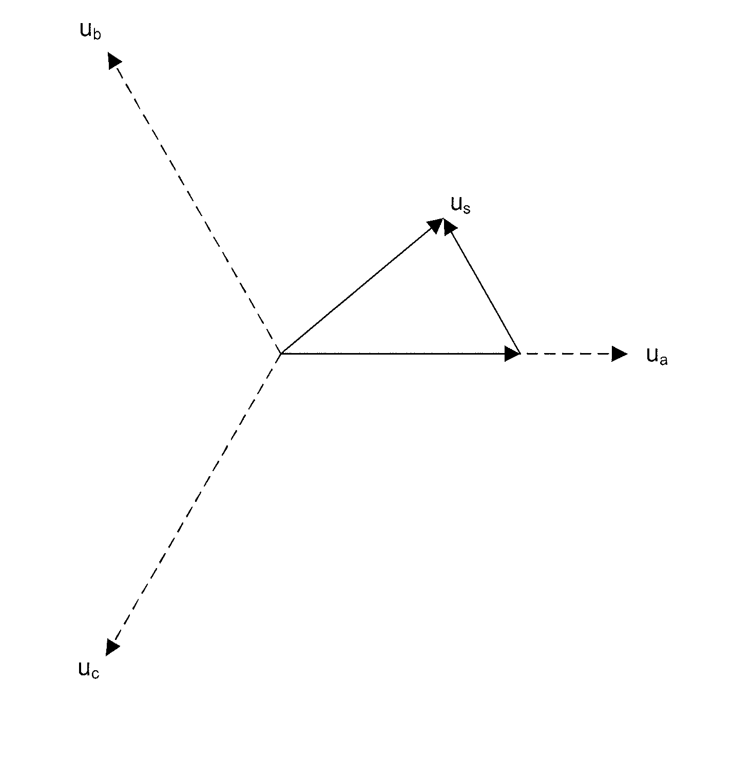
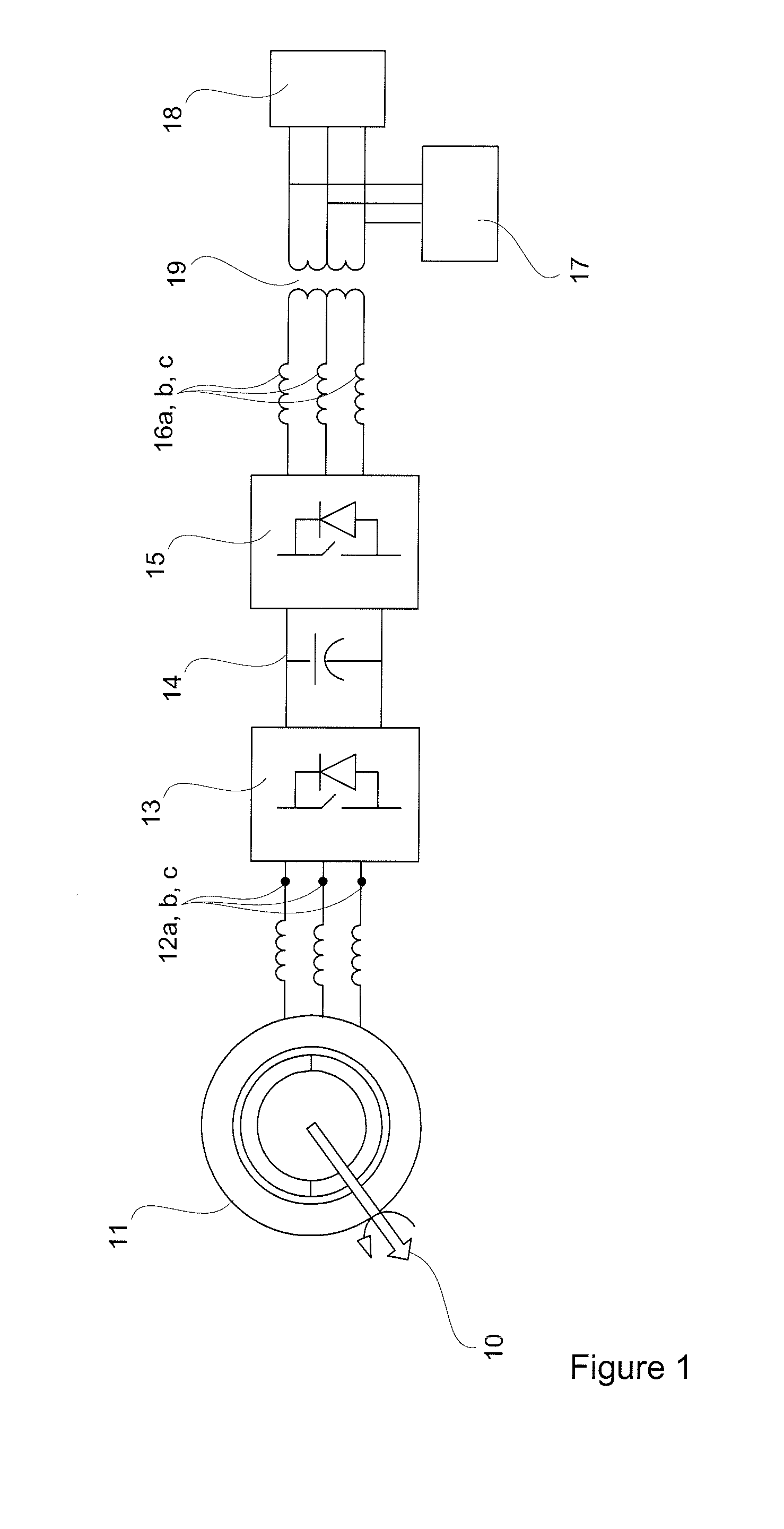
[0089]FIG. 1 illustrates an example of a generator converter system according to a preferred embodiment of the present invention.

[0090]A shaft 10 transfers mechanical energy from an energy source, preferably a set of wind turbine blades (not shown), to a rotor of a variable speed generator 11. The shaft is preferably connected to the wind turbine blades, and to the rotor via a gearbox in order to adapt the rotational speed of the shaft 10 (i.e. speed of the wind turbine blades) to a speed range suitable for the generator 11. The generator 11 then converts the mechanical energy provided via the shaft 10 into electrical energy and delivers the electrical energy at a set of stator terminals 12a, 12b, 12c. For optimum performance in respect of converting the wind energy into electrical energy the shaft 10 will vary its speed as a function of the wind speed. Since the rotational speed of the rotor of the generator 11 is proportional to the rotational speed of the shaft 10, the amplitude ...


PUM


Abstract

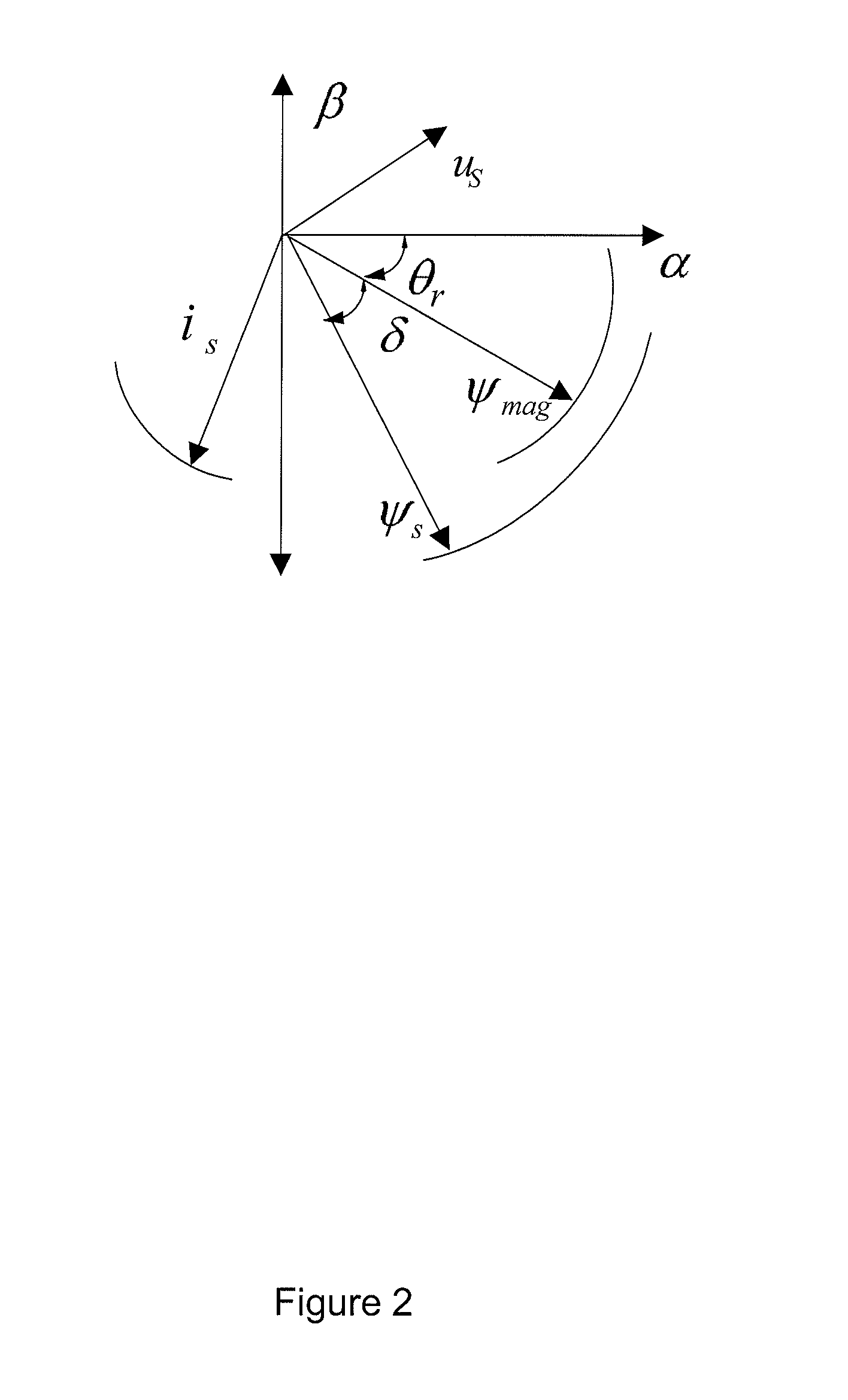
A method for controlling a variable speed wind turbine generator is disclosed. The generator is connected to a power converter comprising switches. The generator comprises a stator and a set of terminals connected to the stator and to the switches of the power converter. The method comprises: determining a stator flux reference value corresponding to a generator power of a desired magnitude, determining an estimated stator flux value corresponding to an actual generator power, determining a difference between the determined stator flux reference value and the estimated stator flux value, and operating said switches in correspondence to the determined stator flux reference value and the estimated stator flux value to adapt at least one stator electrical quantity to obtain said desired generator power magnitude.

Description

TECHNICAL FIELD[0001]The present invention generally relates to power converters, and more specifically to power converters that may be connected to wind turbine generators (WTG) which operate at variable speeds, thereby providing a voltage and current with variable amplitude and frequency.BACKGROUND OF THE INVENTION[0002]Wind has been used for a long time as a source of power and in recent years it has become very common to use the wind for producing electrical power. In order to do so, the power in the wind is captured by a set of blades (normally two or three) of a wind power plant. The wind captured by the blades causes a shaft connected to the blades to rotate. The shaft is connected to a rotor of a generator, which hence rotates at the same speed as the shaft, or at a multiple of the speed of the shaft in case the rotor is connected to the shaft via a gearbox. The generator then converts the mechanical power provided by the wind into electrical power for delivery to a grid.[00...

Claims


Application Information

Patent Timeline
Patent Type & Authority Applications(United States)
IPC IPC(8): H02P21/12
CPCH02P9/105H02P9/107H02P21/0035H02P2101/15H02P23/004H02P27/12H02P21/12H02P23/30H02P21/22
Inventor TRIPATHI, ANSHUMANHELLE, LARSJORGENSEN, ALLAN HOLMYU, CAO SHUGUPTA, SAURABH
Owner VESTAS WIND SYST AS
Learn More