Optical projection system and projector including the same

a technology of optical projection system and projector, applied in the field of optical projection system, can solve the problems of affecting the image quality of the image,

Active Publication Date: 2013-01-10
SEIKO EPSON CORP
View PDF6 Cites 22 Cited by
  • Summary
  • Abstract
  • Description
  • Claims
  • Application Information

AI Technical Summary

Benefits of technology

[0029]Another aspect of the invention is directed to a projector including the optical projection system and the light modulation device. According to the projector, it is possible to project an image, which has an aspect ratio which is different from the aspect rat

Problems solved by technology

However, this type of converter is provided as an external optical section which is independent from the projector main body, causes an increase in the size of the projector, complicates the adjustment of the whole optical projection system including the converter, or badly degrades an image.
If the relay system or the anamorphic converter is used in an optical projection system as

Method used


Image

  • Optical projection system and projector including the same
  • Optical projection system and projector including the same
  • Optical projection system and projector including the same

Examples


first embodiment

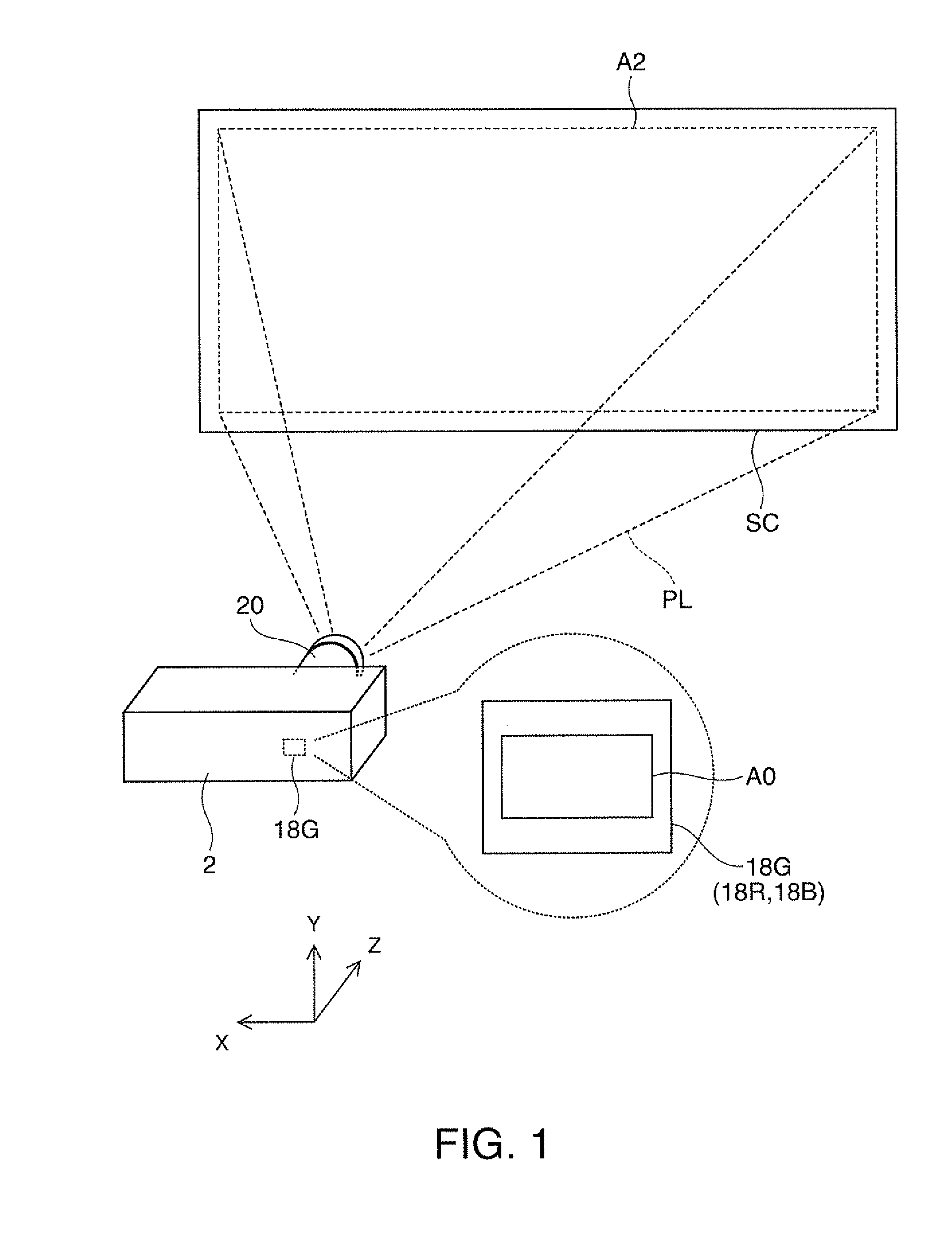
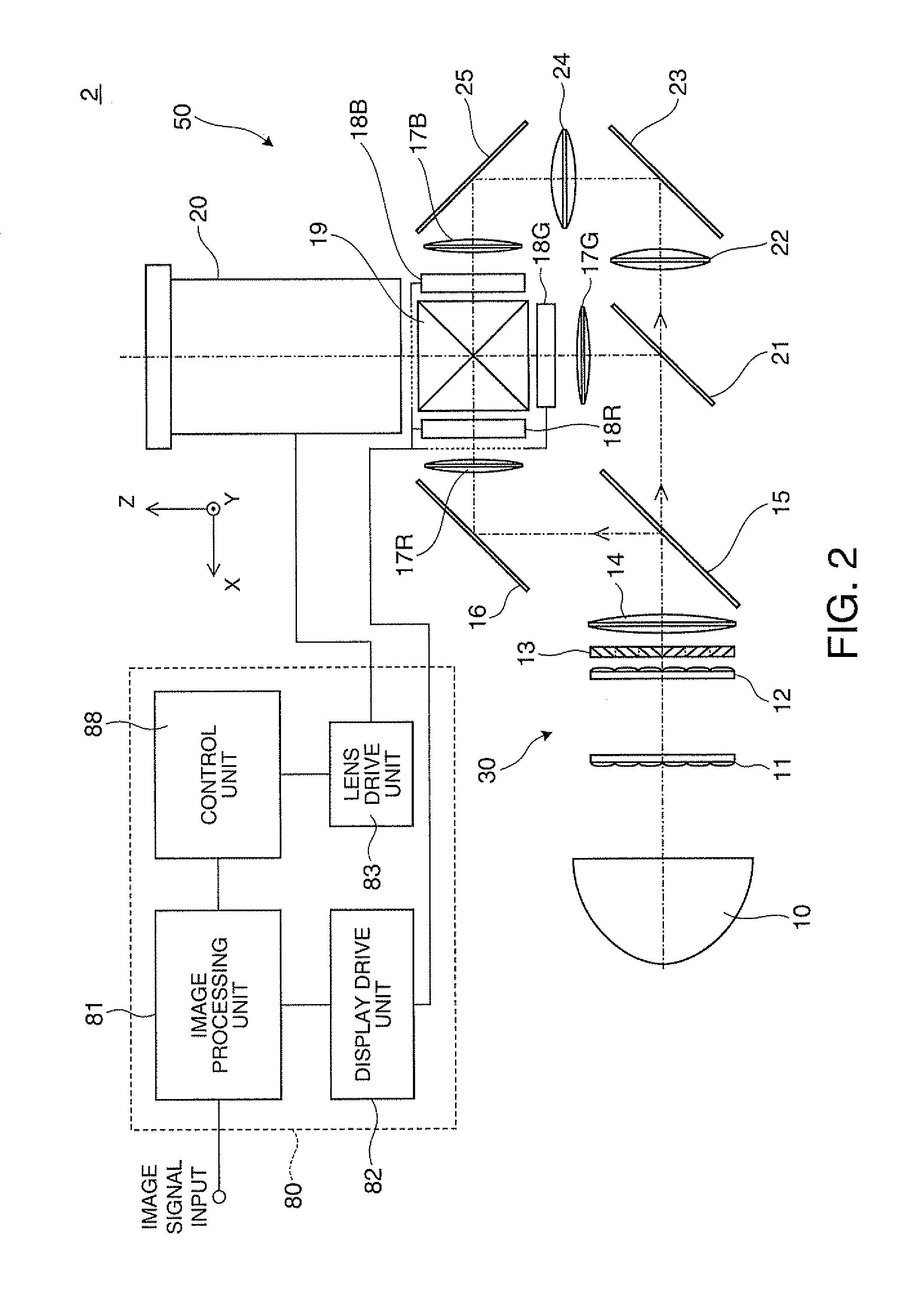
[0067]As shown in FIG. 1, a projector 2 according to a first embodiment of the invention forms image light PL in response to an image signal, and projects the corresponding image light PL on a surface to be projected, such as a screen SC. When the image of a liquid crystal panel 18G (18R, 18B), which is a light modulation device embedded in the projector 2, is enlarged and then projected on the screen (the surface to be projected) SC, the optical projection system 20 of the projector 2 can make the aspect ratio AR0 of the image of the liquid crystal panel 18G (18R, 18B) to be different from the aspect ratio AR2 of an image to be projected on the screen SC. That is, although the aspect ratio AR0 of the display region A0 of the liquid crystal panel 18G can be different from the aspect ratio AR2 of the display region A2 of the screen SC, the aspect ratio AR0 of the display region A0 of the liquid crystal panel 18G carne the same as the aspect ratio AR2 of the display region A2 of the s...

example 1

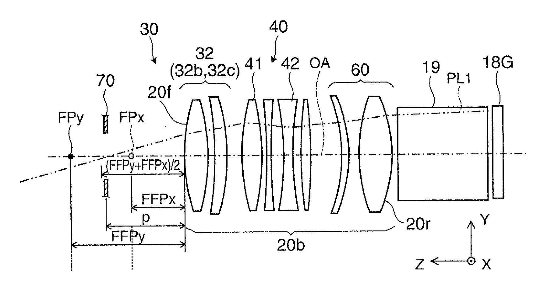
[0123]FIGS. 9 to 11 are views illustrating a detailed Example 1 of the optical projection system 20 of the first embodiment, and illustrate the optical projection system 20 in the first operating state. FIG. 9 illustrates the state of a “tele end”, in which magnification power is comparatively low, with respect to the longitudinal section. FIG. 10 illustrates the state of a “wide end”, in which magnification power is comparatively high, with respect to the longitudinal section. FIG. 11 illustrates the state of the “wide end”, in which magnification power is comparatively high, with respect to the lateral section.

[0124]The optical projection system 20 includes lenses L1 to L21. The first group 30 is configured to include the lenses L1 to L13, the second group 40 is configured to include the lenses L14 to L19, and the third group 60 is configured to include the lenses L20 and L21. The lenses L1 to L13 included in the first group 30 are lenses having rotationally symmetric spherical su...

second embodiment

[0132]Hereinafter, an optical projection system or the like according to a second embodiment will be described. In addition, the second embodiment is the modification example of the optical projection system or the like according to the first embodiment, and portions and items which are not especially described are the same as the case of the first embodiment.

[0133]FIGS. 16A and 16B are views illustrating an optical projection system 20 according to the second embodiment. With respect to the section of the longitudinal direction (Y direction), a second group 240 of the optical projection system 20 includes a first optical device group 241 having negative power, and a second optical device group 242 having positive power in order from the screen SC. In this case, an image can be projected on the screen SC at an aspect ratio obtained by enlarging an image to be formed on the liquid crystal panel 18G (18R, 18B) in the longitudinal direction and compressing in the lateral direction.

[013...


PUM


Abstract

A light modulation device side lens group has different powers in the longitudinal direction and the lateral direction of a liquid crystal panel. Therefore, as the entire system of the optical projection system, the light modulation device side lens group has different magnification in the longitudinal and lateral directions. Therefore, it is possible to make the aspect ratio of an image of the liquid crystal panel different from the aspect ratio of an image projected on a screen. That is, conversion can be performed on an aspect ratio. At this time, a distance p between each focus or a diaphragm and the screen SC side end surface of the light modulation device side lens group satisfies the conditional expressions, so it is possible to achieve a predetermined or higher telecentricity in both states, that is, a first operating state and a second operating state.

Description

BACKGROUND[0001]1. Technical Field[0002]The present invention relates to an optical projection system, which can perform conversion of the aspect ratio of a projected image, and a projector including the same.[0003]2. Related Art[0004]As a converter for aspect ratio conversion, which is used for the optical projection system of a projector, there is a front arrangement-type converter which is arranged to advance and retract in the front of an optical projection system in the related art, that is, in the front of an image side.[0005]However, this type of converter is provided as an external optical section which is independent from the projector main body, causes an increase in the size of the projector, complicates the adjustment of the whole optical projection system including the converter, or badly degrades an image.[0006]In addition, instead of the optical projection system of the projector, as a converter for aspect ratio conversion used in an imaging optical system, such as a ...

Claims


Application Information

Patent Timeline
IPC IPC(8): G02B13/08
CPCG02B13/12G02B13/16G02B13/08G03B21/142G02B27/64G02B13/22
Inventor OTANI, MAKOTOMORIKUNI, EIJI
Owner SEIKO EPSON CORP
Why Eureka
Try Eureka