
Method for the computer-aided control of a technical system

a technology of computer-aided control and technical system, applied in adaptive control, process and machine control, instruments, etc., can solve the problems of only being able to use methods to a limited extent, method does not take into account what information content is actually required, and the complexity of technical systems is usually high, so as to achieve high computational efficiency and accuracy.

Inactive Publication Date: 2013-01-10
SIEMENS AG
View PDF0 Cites 36 Cited by
  • Summary
  • Abstract
  • Description
  • Claims
  • Application Information

AI Technical Summary

Benefits of technology

The invention provides a method for controlling and regulating a technical system using a neural network that models the system's dynamic behavior with high efficiency and accuracy. The output layer of the neural network is influenced only by variables that actually affect the system, ensuring precise and efficient control based on the hidden states in the underlying layer. The method can also be used for non-linear systems and a non-linear activation function can be employed. The evaluation signal used in the neural network is also utilized in the learning and optimization process for an improved evaluation signal.

Problems solved by technology

Nowadays, technical systems usually have a high degree of complexity, that is, they are described by states having a large number of state variables.
In the standard method for controlling or optimizing the dynamic behavior of technical systems as described above, the problem exists that such methods can only be used to a limited extent for technical systems having a large number of state variables and action variables (i.e. in a state space comprising states and actions with a large number of dimensions).
Although the method of said document reduces the number of dimensions in the state space of the hidden layer, the method does not take account of what information content is actually required for modeling the dynamic behavior of the technical system.
This leads to greater errors in the modeling or in the computer-aided control and / or regulation of the technical system.

Method used


Image

  • Method for the computer-aided control of a technical system
  • Method for the computer-aided control of a technical system
  • Method for the computer-aided control of a technical system

Examples


Embodiment Construction

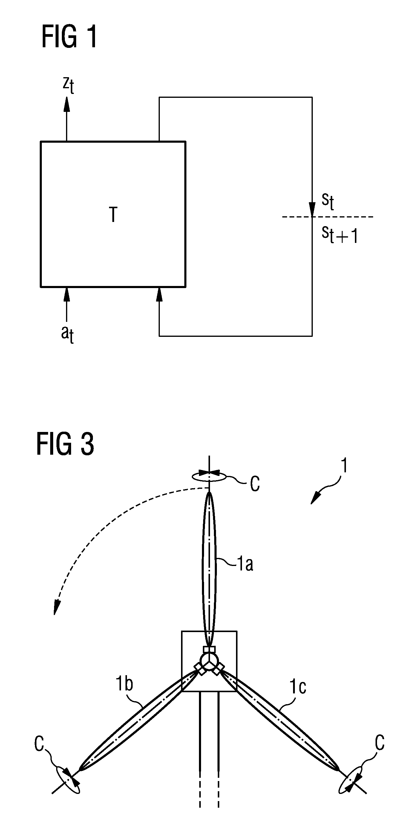
[0032]FIG. 1 shows, in schematic form, the dynamic behavior of a technical system observed in the invention, indicated by a box with the reference sign T. The technical system is described at a time point t by an observable state or an “observable” zt and an action at performed on the technical system. The system contains internal or hidden states st which are not observable. The hidden state st is changed by an action at and is transformed into the state st+1. The state st+1 depends on the action at and the preceding state st. The technical system T is also specified by a suitable evaluation signal (not shown in FIG. 1) which defines the extent to which the action performed in one state of the technical system is evaluated as good with regard to an optimum operation of the technical system. Examples of such evaluation signals are the pollutant emission of the technical system or the mechanical loading and alternating loading of the technical system in operation, wherein the target ...


PUM


Abstract

A method for the computer-aided control of a technical system is provided. A recurrent neuronal network is used for modeling the dynamic behaviour of the technical system, the input layer of which contains states of the technical system and actions carried out on the technical system, which are supplied to a recurrent hidden layer. The output layer of the recurrent neuronal network is represented by an evaluation signal which reproduces the dynamics of technical system. The hidden states generated using the recurrent neural network are used to control the technical system on the basis of a learning and / or optimization method.

Description

CROSS REFERENCE TO RELATED APPLICATIONS[0001]This application is the US National Stage of International Application No. PCT / EP2011 / 052162, filed Feb. 15, 2011 and claims the benefit thereof. The International application claims the benefits of German application No. 10 2010 011 221.6 DE filed Mar. 12, 2010. All of the applications are incorporated by reference herein in their entirety.FIELD OF INVENTION[0002]The invention relates to a method for the computer-aided control and / or regulation of a technical system and a corresponding computer program product.BACKGROUND OF INVENTION[0003]Nowadays, technical systems usually have a high degree of complexity, that is, they are described by states having a large number of state variables. In addition, many different actions can be carried out on the technical system based on relevant action variables. The state variables are, in particular, measurable state values of the technical system, for example, physical variables such as pressure, te...

Claims


Application Information

Patent Timeline
IPC IPC(8): G06N3/08
CPCG05B13/027
Inventor DULL, SIEGMUNDSTERZING, VOLKMARUDLUFT, STEFFEN
Owner SIEMENS AG
Learn More