

Mechanical locking system for floor panels
a technology of locking system and floor panel, which is applied in the direction of floor, ladder, building components, etc., can solve the problems of reducing strength, affecting the stability of the floor, and reducing the strength of the clamping connection, so as to achieve high precision, low material and production costs, and reliable over time
- Summary
- Abstract
- Description
- Claims
- Application Information
AI Technical Summary
Benefits of technology
Problems solved by technology
Method used
Image

Examples
Embodiment Construction
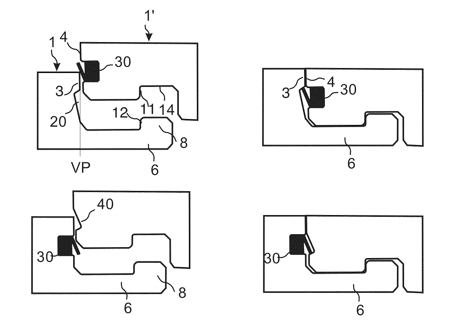
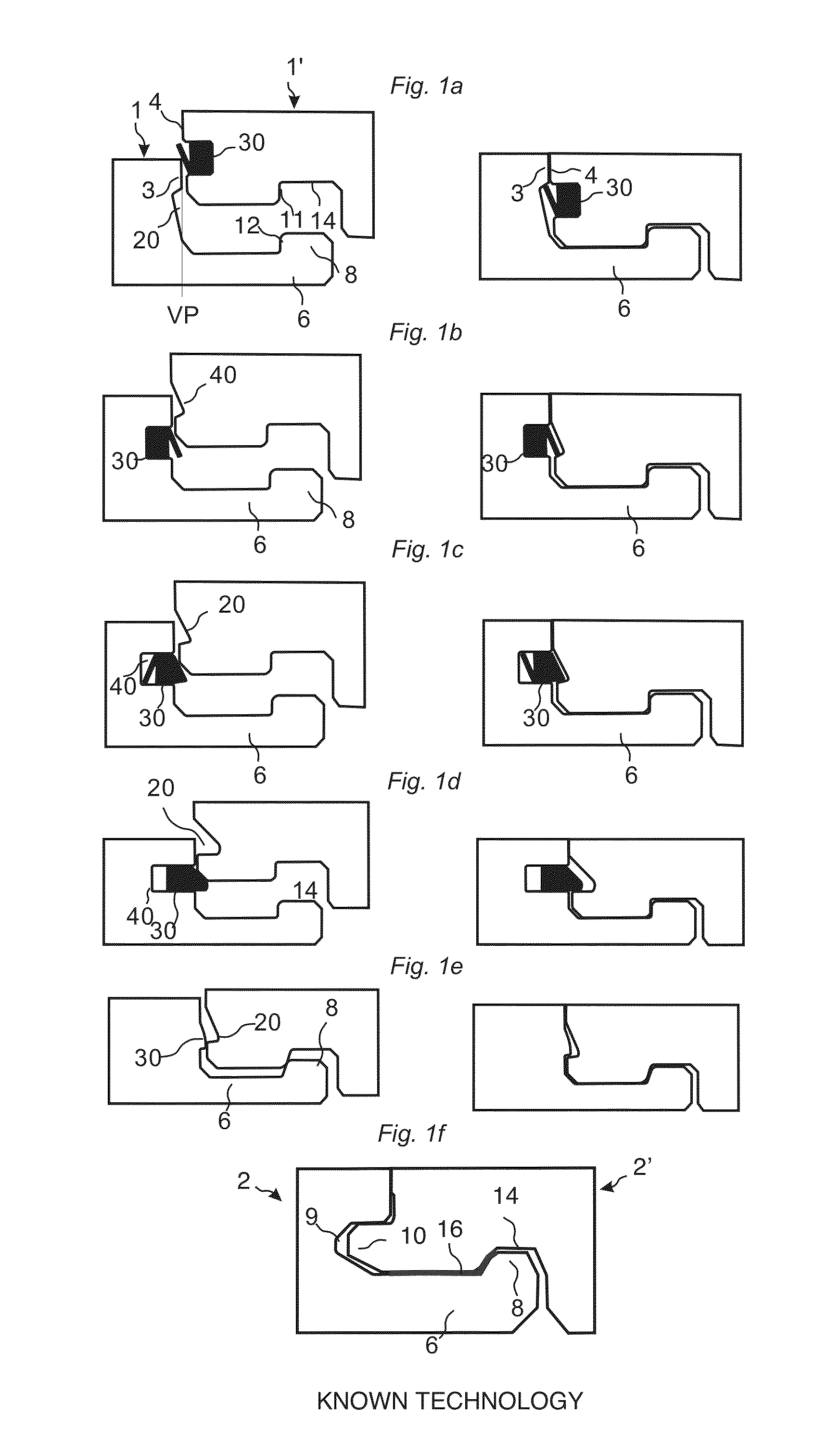
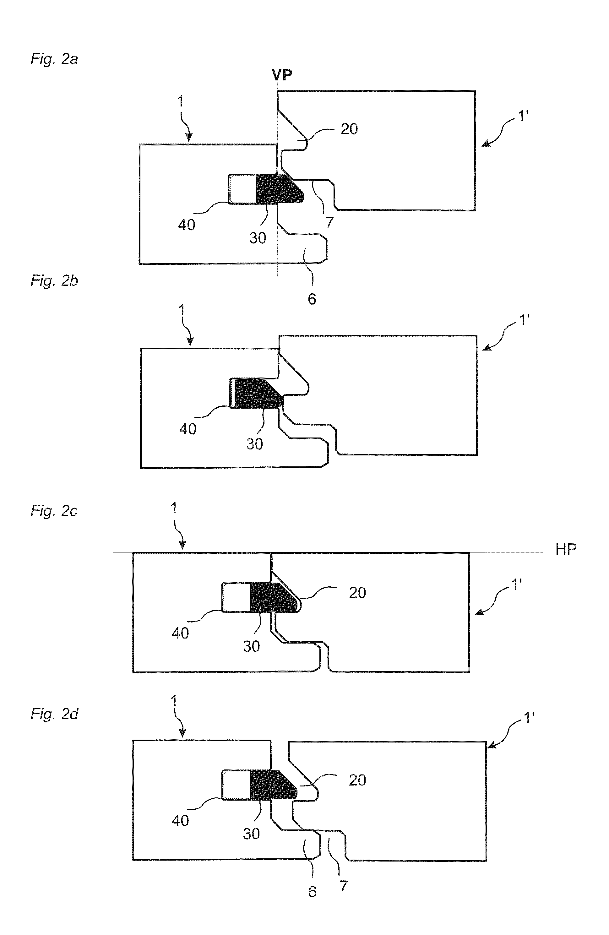
[0087]To facilitate understanding, several locking systems in the figures are shown schematically. It should be emphasised that improved or different functions may be achieved using combinations of the preferred embodiments.
[0088]The inventor has tested all known and especially all commercially used locking systems on the market that are installed with vertical folding in all type of floor panels, especially laminate and wood floorings and the conclusion is that at least all these known locking systems which have one or more locking elements cooperating with locking grooves may be adjusted to a system with a slide lock on the long edges which prevents displacement along the adjacent edges and with fold down locking system on short edges that only locks vertically.
[0089]The most preferable embodiments are however based on floorboards with a surface layer of laminate, powder based paper free surfaces or wood surfaces, a core of HDF or wood and a locking system on the long edge with a ...
PUM
 Abstract
Description
Claims
Application Information