Mass flow sensor and method for determining the mass flow in a pipe

a mass flow sensor and mass flow technology, applied in the direction of mass flowmeters, volume/mass flow by dynamic fluid flow effect, instruments, etc., can solve the problems of long flow time loss, large calibration expenditure, and high measurement errors, so as to avoid pressure loss and achieve the effect of considerably more accurate measurement results

Inactive Publication Date: 2013-01-17
KARLSRUHER INST FUR TECH
View PDF3 Cites 6 Cited by
  • Summary
  • Abstract
  • Description
  • Claims
  • Application Information

AI Technical Summary

Benefits of technology

[0012]A further object is to provide a mass flow sensor which operates reliably in the area surrounding strong electro-magnetic fields, which is suitable for use with gases as well as liquids, and which can also be used at extremely low temperatures, especially in the field of cryogenic technology, wherein this sensor need not be inserted into the mass flow, thereby avoiding a pressure loss occurring in the flow.
[0024]In addition to the one or several gaps existing between the wall element and the pipe wall into which the wall element is inserted or integrated, the pipe according to one embodiment also contains one or several openings (bore holes) which connect the pipe inside with the chamber. A share of the mass flow enters from the pipe into the chamber through the at least one gap and / or the at least one opening, thus ensuring that the same temperature as in the mass flow is also present in the chamber. The accuracy of the temperature measurement is clearly increased in this way.
[0028]According to another embodiment, a small share of the mass flow enters the chamber through the at least one gap between the wall element and the pipe wall and, insofar as present, through at least one additional opening in the pipe. As a result, it is ensured that the chamber has the same temperature as the mass flow, so that the temperature of the mass flow can be determined with a temperature sensor. The change in length of an additional section of at least one glass fiber which is not clamped in between a chamber wall and the wall element is preferably determined for this with the aid of a thereon installed strain gauge in the form of a FBG sensor. In this way it is possible to subtract out a share of the length change in one or several of the expandable connections, meaning glass fibers, caused by a temperature change and not caused by the effect of the shearing stress.
[0029]The mass flow sensor according to the invention is not dependent on the amount of hydraulic pressure, thus making it possible to determine the mass flow in liquid flows as well as in gas flows.
[0030]With the mass flow sensor according to the invention, no additional pressure loss is incurred as compared to a regular pipe flow and / or a conduit flow since the movable wall element which absorbs the shearing stress of the flow is inserted into the wall of the pipe or the pipe section. The mass flow sensor according to the invention avoids pressure losses by avoiding the installation of any device which could result in additional loss of pressure as compared to an unobstructed pipe flow and / or conduit flow. According to the invention, the movable wall element is instead moved only by the wall shearing stress which occurs in any case in the pipe and / or conduit. Consequently, the shearing stress and not the compression force is the actual input variable in this case for determining the volume of the mass flow.
[0031]An embodiment of the mass flow sensor according to the invention provides information on whether the change in the glass fiber length is actually caused by the change in the flow resistance of the mass flow to be examined and not as a result of a temperature change. This information is obtained by determining only the temperature with the aid of an additional FBG sensor. As a result, the absolute flow temperature of the mass flow is measured in on the one hand while, on the other hand, the change in length caused by the temperature influence is also clearly determined, thus making the measuring results considerably more accurate.

Problems solved by technology

Conventional mass flow sensors for determining the mass flow of a fluid, meaning a liquid or a gas, on the one hand are based on a use of differential pressure methods which, however, cause a lasting pressure loss in the flow as a result of the measuring operation and, on the other hand, are based on electronic methods which are influenced considerably by strong electromagnetic fields in the area surrounding the sensor, thereby resulting in high measuring errors or in a considerable calibration expenditure.
The disadvantage of this arrangement is that a noticeable hydraulic pressure is generated only in a liquid, so that the device is not suitable for use with gas flows.
The device furthermore requires a deformable element which is an essential disadvantage, in particular with extreme changes in temperature during which the material characteristics of this element can change considerably, as well as at low temperatures since practically no deformable materials exist, which can be used at these temperatures.
This sensor has the disadvantage of being located in the flow, thereby resulting in a higher pressure loss as compared to an unobstructed pipe and / or conduit flow.
A further disadvantage is that the sensor detects the flow-characteristic Kámán vortices with the aid of a FBG sensor.
As a result, it is impossible to determine whether the length change in the flow meter occurs as a result of the change in the flow resistance or only as a result of a temperature change.
The disadvantage of this arrangement is that a flow must be directed toward the measuring arrangement, so that it is not suitable for measuring an inside flow and thus is not suitable without problems as a mass flow sensor.
The installation inside a pipe would result in considerable pressure loss.
The disadvantage of this arrangement is that the reinforced glass fiber must be inserted into the flow, thereby causing an additional pressure loss.
In contrast to a liquid flow, a gas flow requires an increase in the number of flow-shaped elements and in the size of the elements, thereby further increasing the pressure loss, wherein it is an additional disadvantage that no distinction can again be made to determine whether the glass fiber expansion is due to the change in the flow resistance or to a temperature change.
This arrangement has the disadvantage that the signal changes as a result of electromagnetic fields, wherein this requires a calibration of the sensor in the magnetic field with respect to size and orientation of the sensor relative to the magnetic field.
In particular when using the sensors in the presence of cryogenic temperatures having magnetic fields impressed from the outside, the calibration expenditure is considerable.
A disadvantage in this case is that the mechanical stress on the rod depends on the temperature as well as on the purity and structure of the material: impurities or occlusions as well as voids influence the ductility of the rod.
Furthermore, owing to the fact that micro-resonators are not sufficiently reproducible, as well as the production of the technically demanding connection between the micro-resonator and the glass fiber, each sensor is a unique device to be calibrated separately.
Finally, the bending of the rod not only results in mechanical stress exerted on the micro-sensor, but also leads to a displacement in flow direction, thereby considerably influencing the signal.
The reversibility of the movement and taking this into consideration within the framework of a calibration are therefore not necessarily ensured, wherein this also detrimentally affects the permanent functionality of the sensor.
The disadvantage of these arrangements is that the mechanical stress for bending the rod again depends on the temperature as well as on the purity and structure of the material.
Since this behavior can be ignored only within an extremely small angular region, it considerably reduces the area of application for the device in flows.

Method used


Image

  • Mass flow sensor and method for determining the mass flow in a pipe
  • Mass flow sensor and method for determining the mass flow in a pipe

Examples


Embodiment Construction

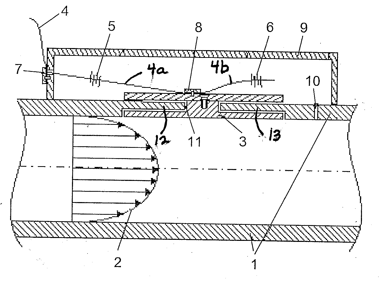
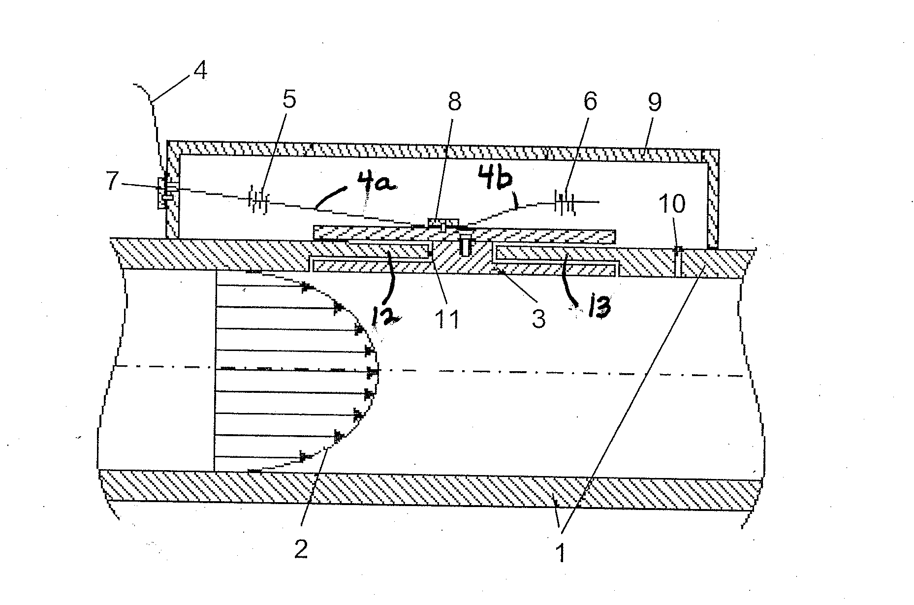
[0036]The single Figure shows a pipe 1 section through which a mass flow 2 of a fluid flows, meaning a gas or a liquid. A movable wall element 3, comprising an inside that faces the mass flow 2 and an outside facing away from the mass flow 2, is located in one section of the pipe 1 wall. Attached to the outside of the movable wall element 3, in a chamber 9 that is sealed against the environment, is a glass fiber functioning as expandable connection 4 which contains a first fiber Bragg grating as strain gauge 5 as well as a second fiber Bragg grating functioning as temperature sensor 6. With low pre-stressing, the glass fiber expandable connection 4 is attached with the aid of a first clamping device 7 to one wall of the chamber 9 and with the aid of a second clamping device 8 to the movable wall element 3. The first fiber Bragg grating functioning as the strain gauge 5 is mounted on the section of the glass fiber that functions as expandable connection 4 and is located between the f...


PUM


Abstract

A sensor for determining a mass flow of a fluid in a pipe includes a wall element adapted for insertion into a cutout in a wall of the pipe through which a mass flow can flow, so that at least one gap remains between the wall element and the wall of the pipe, and so that the wall element is positionable on the outside facing away from the mass flow. A sealed chamber is adapted to enclose the wall element on the outside of the pipe. At least one expandable connection is located in the sealed chamber and is clamped in between the wall element and one wall of the chamber. At least one strain gauge comprising a fiber Bragg grating sensor is located on a section of the expandable connection that is clamped in between the wall of the chamber and the wall element.

Description

CROSS-REFERENCE TO RELATED APPLICATION[0001]This application is a National Stage application of International Application No. PCT / EP2011 / 001312, filed Mar. 17, 2011, which claims the priority benefit of German Application No. 10 2010 012 924.0, filed on Mar. 26, 2010.BACKGROUND OF THE INVENTION[0002]The invention relates to a sensor for determining the mass flow of a fluid (mass flow sensor), to a pipe provided with a mass flow sensor of this type, as well as to a method for determining the mass flow of a fluid in a pipe.[0003]Conventional mass flow sensors for determining the mass flow of a fluid, meaning a liquid or a gas, on the one hand are based on a use of differential pressure methods which, however, cause a lasting pressure loss in the flow as a result of the measuring operation and, on the other hand, are based on electronic methods which are influenced considerably by strong electromagnetic fields in the area surrounding the sensor, thereby resulting in high measuring erro...

Claims


Application Information

Patent Timeline
Patent Type & Authority Applications(United States)
IPC IPC(8): G01F1/28
CPCG01F1/86G01F1/28
Inventor NEUMANN, HOLGERRAMALIGAM, RAJINI KUMARSUESSER, MANFRED
Owner KARLSRUHER INST FUR TECH
Why Eureka
Try Eureka