Wind power plant with optimal power output

a wind power plant and optimal technology, applied in the direction of ac network voltage adjustment, ac circuit arrangement, single network parallel feeding arrangement, etc., can solve the problems of lvrt and subsequently disconnect from the grid, the number of lvrt is not strong enough to support the amount of electrical power, and the solution is expensive and time-consuming. achieve the effect of faster increase in power

Active Publication Date: 2013-01-17
VESTAS WIND SYST AS
View PDF5 Cites 45 Cited by
  • Summary
  • Abstract
  • Description
  • Claims
  • Application Information

AI Technical Summary

Benefits of technology

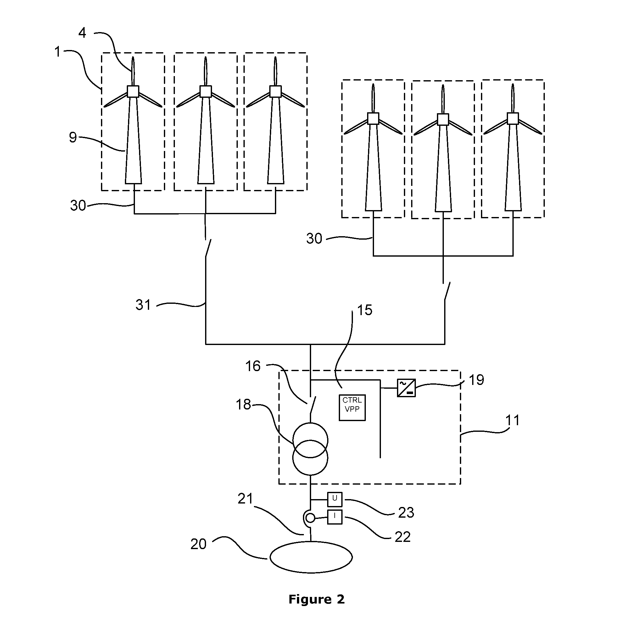
[0018]An advantage of this embodiment is that the voltage level is monitored in respect to the increase of power, which will allow a faster increase in power, since the power increase is controlled in relation to the actual voltage level and not in respect to a pre-calculated model of the electrical grid.
[0019]Another advantage of this embodiment is that the actual measurement of the impedance is not needed. Instead the change in voltage level as a function of increased power (dV / dP or dV / dQ) is monitored.

Problems solved by technology

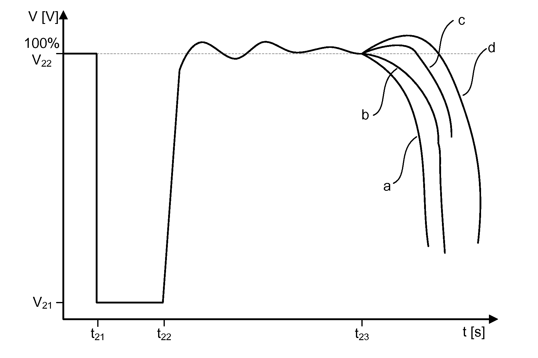
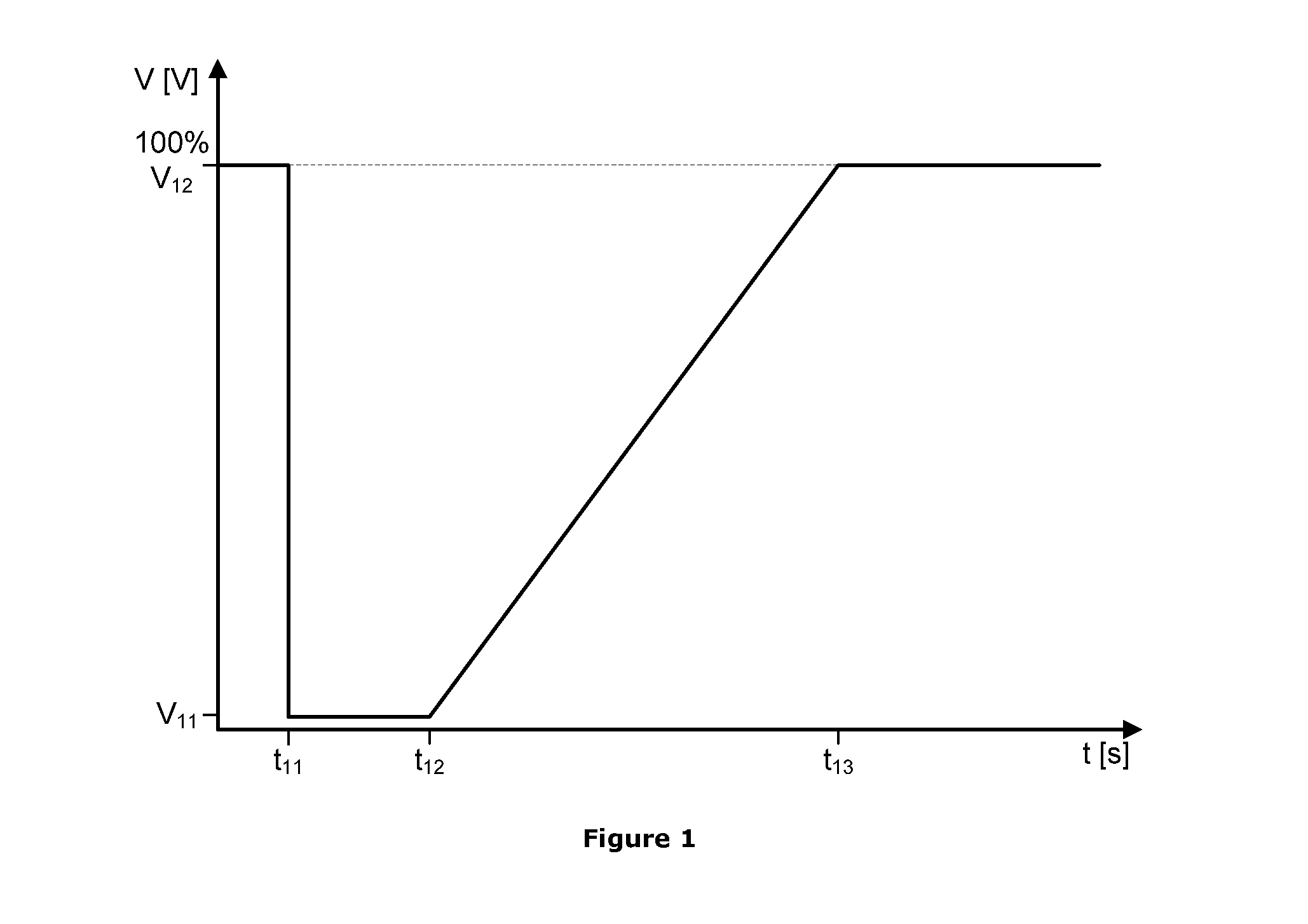
It has been shown that a problem exists in the case where a wind power park experiences a LVRT (low voltage ride through) or other failure modes in the electrical grid.
Even though the voltage level V is at the intended value and from the wind power plant side of view, everything is fine; the grid may not be strong enough to support the amount of electrical power.
Thus, at voltage control of at wind power plant, a LVRT occurring as a fault in the grid, may result in the wind power plant induces a number of LVRT and subsequently disconnects from the grid.
This solution is of course expensive and time-consuming.
Another consequence of this is often that the amount of installed capacity of wind power is lower than the actual potential of the wind site.
Both documents help to solve the problem of operating the grid in a stable mode, but it might not be a solution that allows the largest penetration of electrical power into the grid and it might not be the fastest way to overcome an LVRT event.

Method used


Image

  • Wind power plant with optimal power output
  • Wind power plant with optimal power output
  • Wind power plant with optimal power output

Examples


Embodiment Construction

[0039]The present invention will now be explained in further details. While the invention is susceptible to various modifications and alternative forms, specific embodiments have been disclosed by way of examples. It should be understood, however, that the invention is not intended to be limited to the particular forms disclosed. Rather, the invention is to cover all modifications, equivalents, and alternatives falling within the spirit and scope of the invention as defined by the appended claims.

[0040]When operating an electrical power grid it is important to maintain a stable grid. A stable grid is an electrical grid, which is robust in respect to changes in the grid, the changes could be, but not limited to, sudden change in the phase angle, load shedding, increase in power production or worse short circuits. As a measure of the stability of the grid, the short circuit ratio (SCR) is often used, the higher SCR means higher stability level of the grid.

[0041]Often wind power plants...


PUM


Abstract

Controlling a wind power plant comprising at least one wind turbine generator for producing power to an electrical grid where the amount of said power is based on a signal response in a voltage signal in said electrical grid due to a change in power output into said electrical grid.

Description

FIELD OF THE INVENTION[0001]The present invention relates to a method for controlling a wind power plant comprising at least one wind turbine generator for producing power to an electrical grid. Moreover the invention relates to a wind power plant comprising at least one wind turbine generator for producing power to an electrical grid.BACKGROUND OF THE INVENTION[0002]A wind power plant (WPP) is an energy converting system consisting of one or more wind turbine generator(s), which converts kinetic wind energy into electrical energy for utility power grids. Specifically, wind is applied to wind turbine blades of the wind turbine to rotate a rotor. The mechanical energy of the rotating rotor in turn is converted into electrical energy by an electrical generator. The electrical energy from the wind turbine generator(s) is fed into an electrical grid at a point of common coupling (PCC).[0003]It has been shown that a problem exists in the case where a wind power park experiences a LVRT (l...

Claims


Application Information

Patent Timeline
Patent Type & Authority Applications(United States)
IPC IPC(8): H02P9/04
CPCH02J3/16H02J3/386H02J2003/001Y02E40/34Y02E10/763H02J3/001H02J2300/28H02J3/381H02J3/48H02J3/50H02J3/46Y02E10/76Y02E40/30
Inventor HESSELB.AE BUTTED.K, BOZAMASTIL, MARTIN HOGDAHL
Owner VESTAS WIND SYST AS
Why Eureka
Try Eureka