Buffy coat separator float systems and methods

a technology of float system and buffy coat, which is applied in the direction of separation process, fluid controller, laboratory glassware, etc., can solve the problems of difficult measurement and low number of cells expected to be typically present in the buffy coat, and achieve the effect of reducing the rotational speed and reducing the pressure of the compressible material against the flexible sleev

Inactive Publication Date: 2013-01-17
BATTELLE MEMORIAL INST
View PDF10 Cites 24 Cited by
  • Summary
  • Abstract
  • Description
  • Claims
  • Application Information

AI Technical Summary

Benefits of technology

[0010]Disclosed herein are methods of separating and axially expanding buffy coat constitutents in a blood sample; detecting target cells in a blood sample; and capturing or extracting buffy coat constitutents/target cells in a blood sample. Those methods require introducing the blood sample and a rigid volume-occupying float into a flexible sample tube. The rigid float has a specific gravity intermediate that of red blood cells and plasma, and comprises a main body portion spacedly surrounded radially by the sidewall of the sample tube to form an annular volume therebetween; and one or more support members protruding from the main body portion and engaging the sidewall. The sample tube is centrifuged at a rotational speed that causes enlargement of the sidewall to a diameter sufficiently large to permit axial movement of the float, separation of the blood into discrete layers, and movement of the float into alignment with at least the buffy coat constituents of the blood sample. The...

Problems solved by technology

However, the number of cells expected to be typically present in the buffy coat is very low relative to the volume of blood, for example, in the range of about 1-100 cel...

Method used


Image

  • Buffy coat separator float systems and methods
  • Buffy coat separator float systems and methods
  • Buffy coat separator float systems and methods

Examples


Embodiment Construction

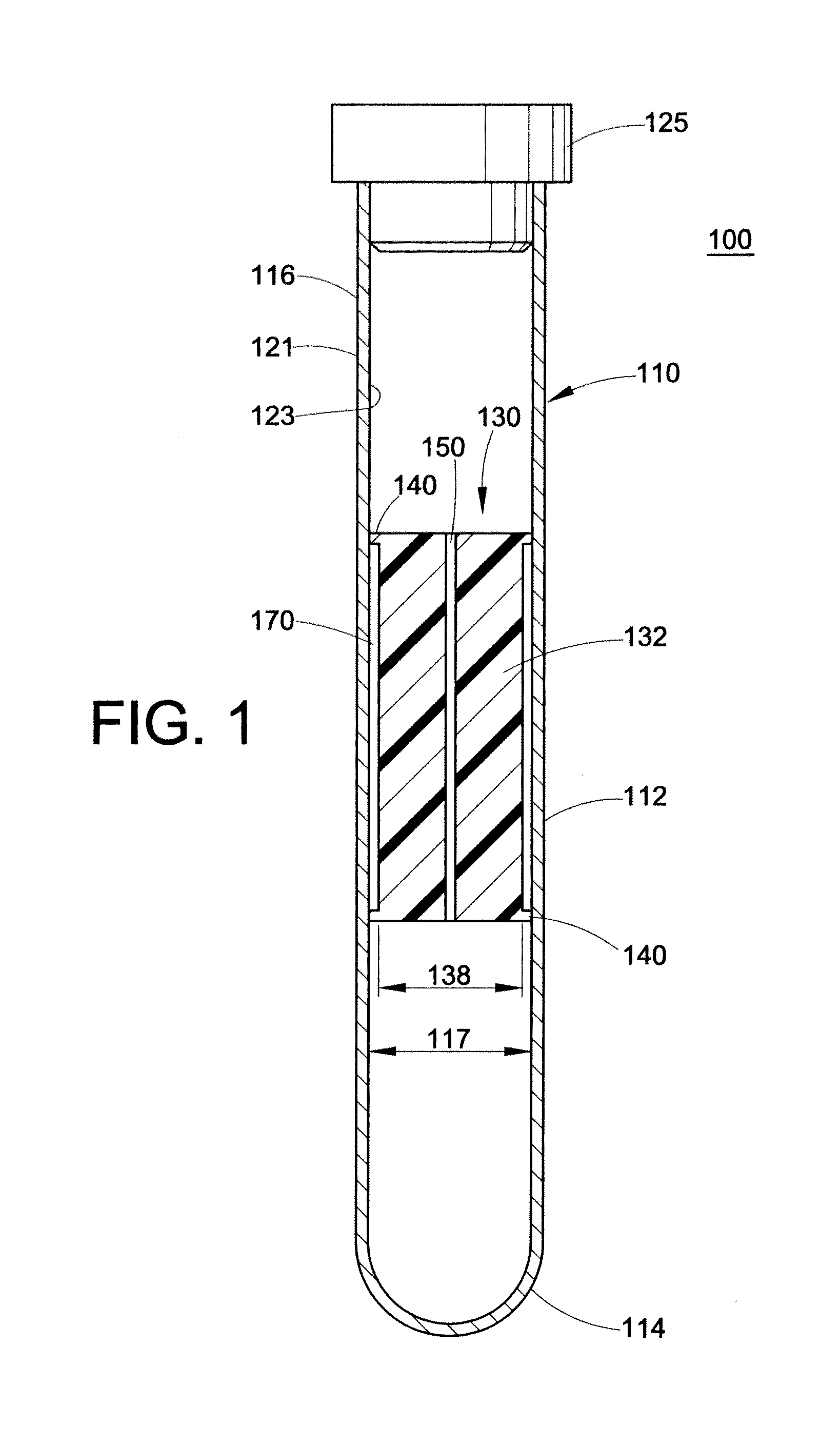
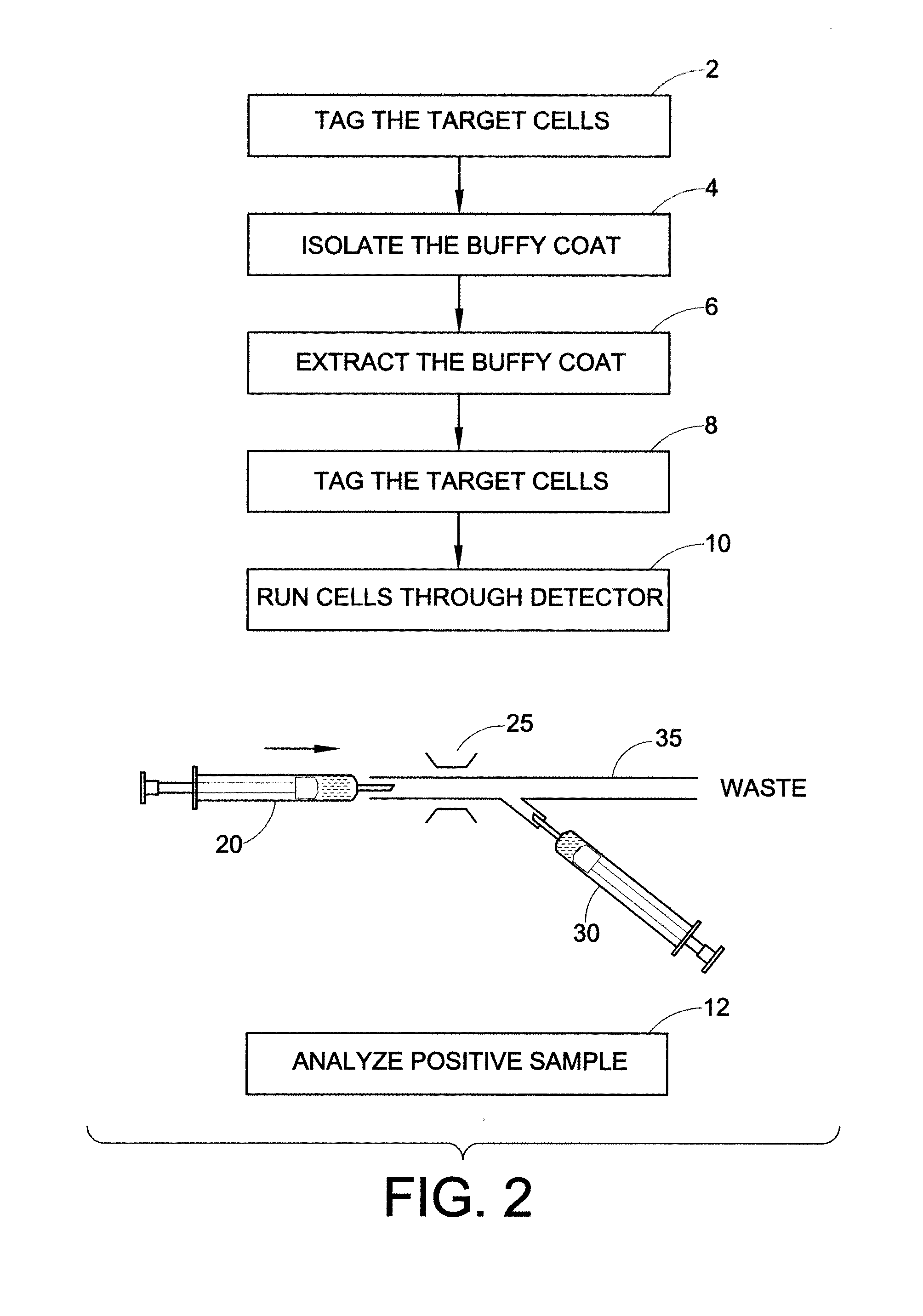
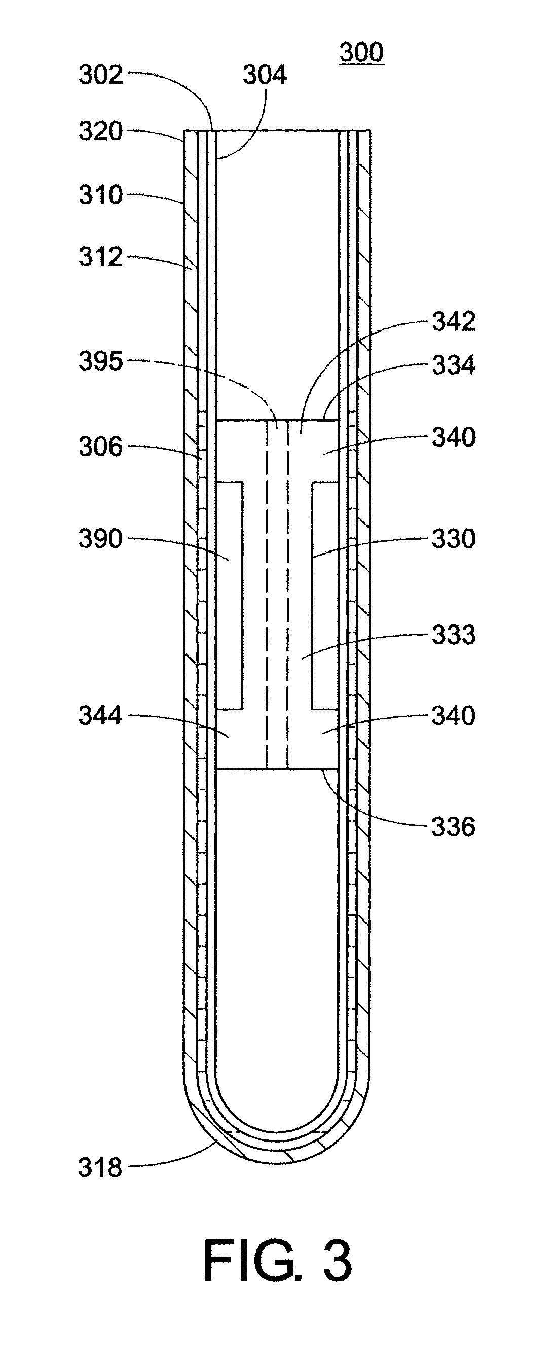
[0046]A more complete understanding of the components, processes, and apparatuses disclosed herein can be obtained by reference to the accompanying drawings. These figures are merely schematic representations based on convenience and the ease of demonstrating the present disclosure, and are, therefore, not intended to indicate relative size and dimensions of the devices or components thereof and / or to define or limit the scope of the exemplary embodiments.

[0047]Although specific terms are used in the following description for the sake of clarity, these terms are intended to refer only to the particular structure of the embodiments selected for illustration in the drawings, and are not intended to define or limit the scope of the disclosure. In the drawings and the following description below, it is to be understood that like numeric designations refer to components of like function.

[0048]The modifier “about” used in connection with a quantity is inclusive of the stated value and has...


PUM

PropertyMeasurementUnit
Lengthaaaaaaaaaa
Pressureaaaaaaaaaa
Diameteraaaaaaaaaa

Abstract

Tube and float systems for separation and axial expansion of the buffy coat are provided. Generally, the systems include a flexible sample tube and a rigid separator float having a specific gravity intermediate that of red blood cells and plasma. The sample tube has an elongated sidewall having a first cross-sectional inner diameter. The float has a main body portion and one or more support members protruding from the main body portion to engage and support the sidewall of the sample tube. During centrifugation, the centrifugal force enlarges the diameter of the tube to permit density-based axial movement of the float in the tube. After centrifugation is ended, the tube sidewall returns to its first diameter, thereby capturing the float and trapping the buffy coat constituents in an annular volume. Several different systems for capturing and retrieving the buffy coat constituents are described.

Description

[0001]This application claims priority to U.S. Provisional Patent Application Ser. No. 61 / 318,929, filed on Mar. 30, 2010, and to U.S. Provisional Patent Application Ser. No. 61 / 372,905, filed on Aug. 12, 2010. The disclosure of these applications is hereby fully incorporated by reference.BACKGROUND OF THE DISCLOSURE[0002]The present disclosure relates generally to density-based fluid separation, and in particular to improved sample tubes and float designs for the separation, identification, and / or quantification of fluid compounds by axial expansion, and methods employing the same. The present disclosure finds particular application in blood separation and axial expansion of the buffy coat layers, and will be described with particular reference thereto.[0003]Quantitative Buffy Coat (QBC) analysis is routinely performed in clinical laboratories for the evaluation of whole blood. The buffy coat is a series of thin, light-colored layers of white cells that form between the layer of re...

Claims


Application Information

Patent Timeline
IPC IPC(8): G01N1/34
CPCB01L3/50215B01L2400/0633B01L2300/0858
Inventor HAUBERT, THOMAS D.
Owner BATTELLE MEMORIAL INST
Why Eureka
Try Eureka