Design and Apparatus of a Magnetic Resonance Multiphase Flow Meter

a multi-phase flow meter and design technology, applied in mechanical equipment, liquid/fluent solid measurement, instruments, etc., can solve the problems of cumbersome and expensive building measurement devices at each location

Active Publication Date: 2013-01-17
BAKER HUGHES INC
View PDF14 Cites 15 Cited by
  • Summary
  • Abstract
  • Description
  • Claims
  • Application Information

AI Technical Summary

Problems solved by technology

Building measurement device at each loca

Method used


Image

  • Design and Apparatus of a Magnetic Resonance Multiphase Flow Meter
  • Design and Apparatus of a Magnetic Resonance Multiphase Flow Meter
  • Design and Apparatus of a Magnetic Resonance Multiphase Flow Meter

Examples


first embodiment

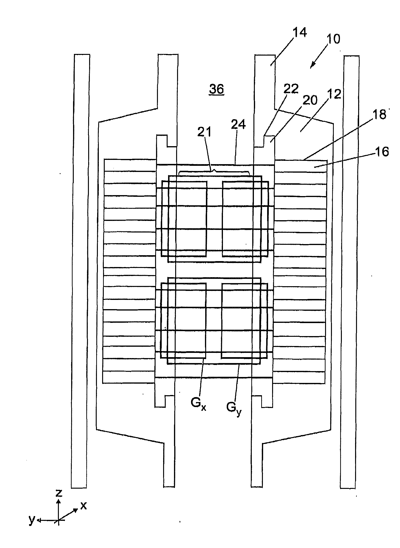
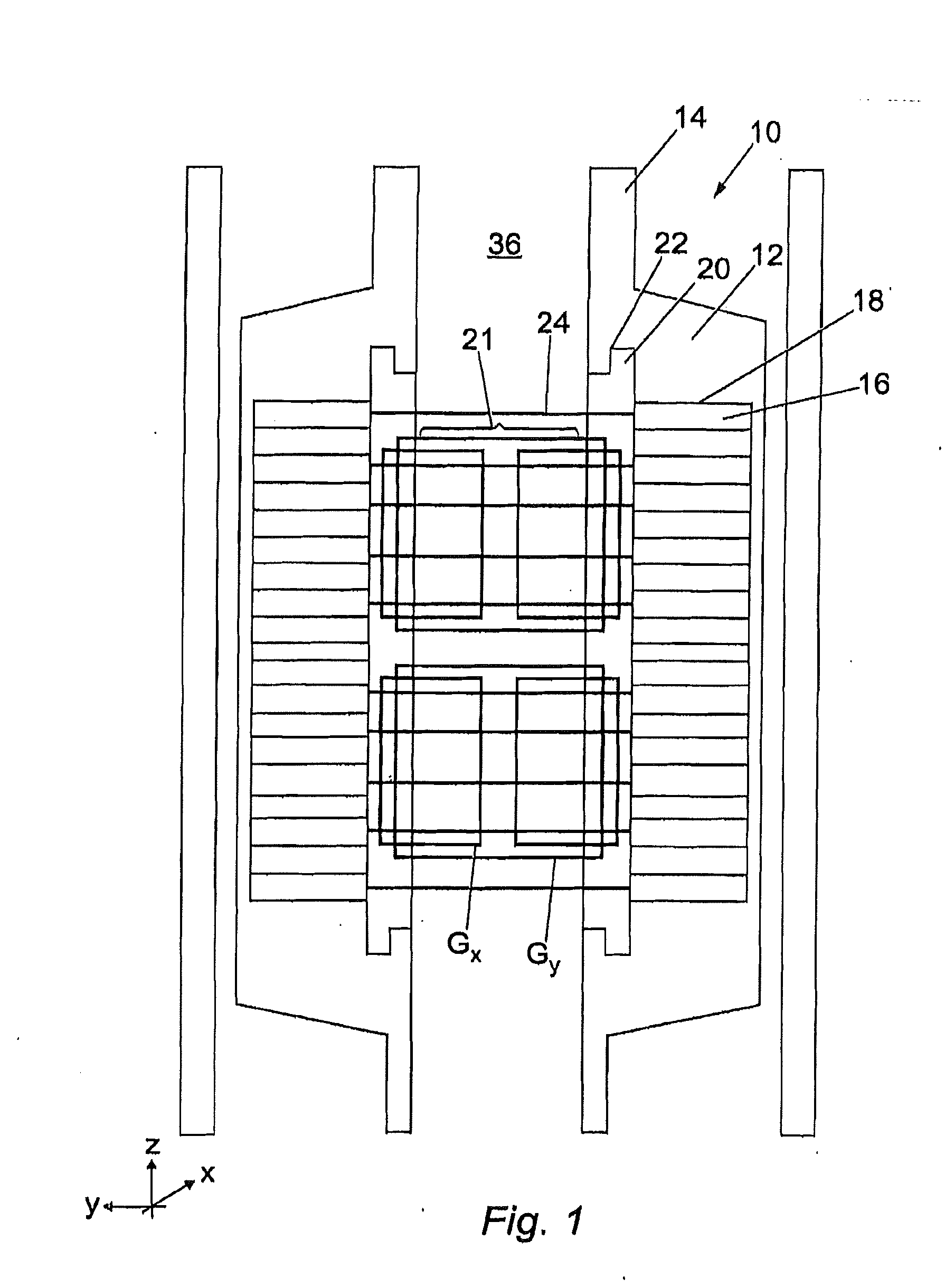
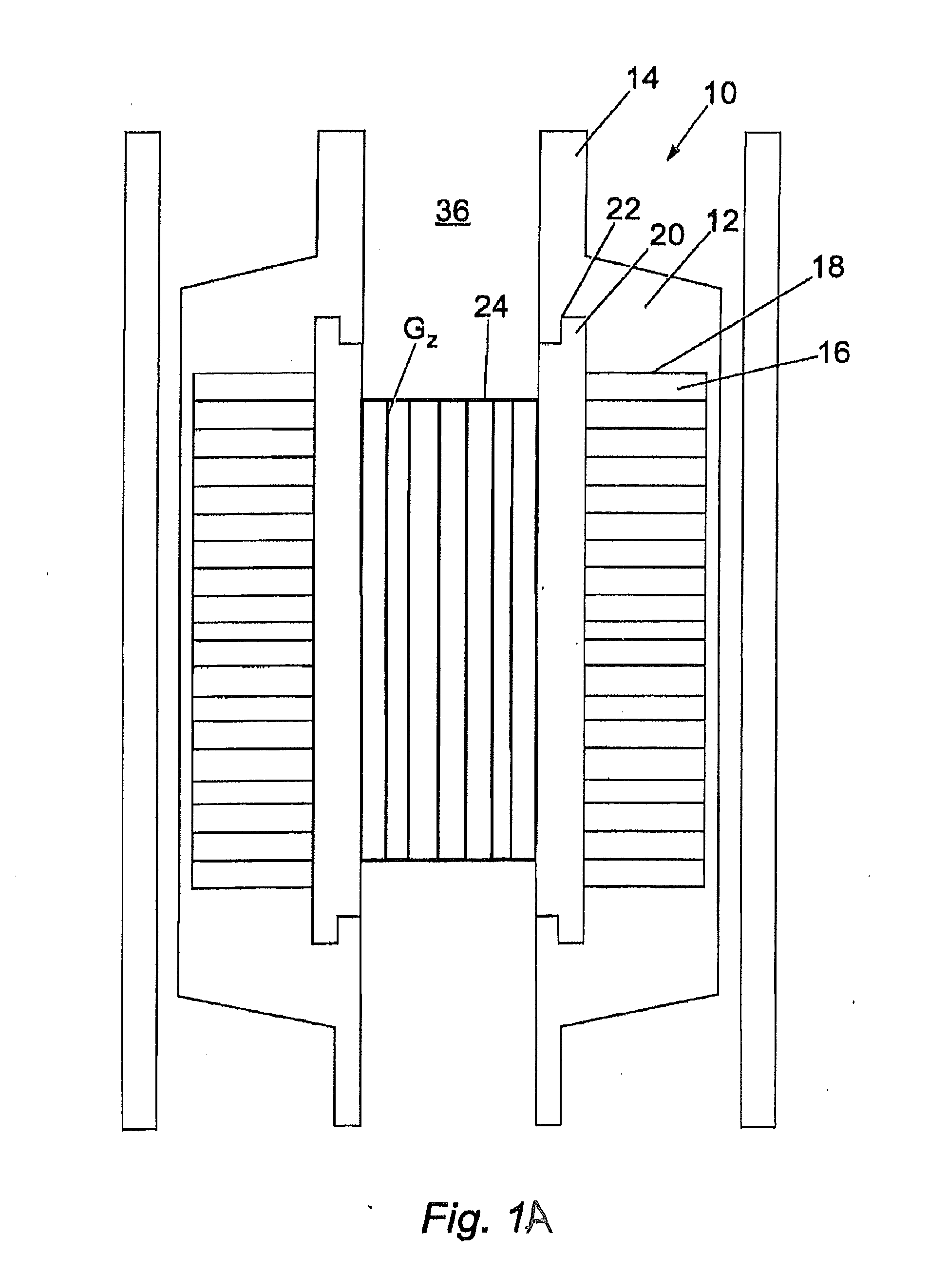
[0029]Referring to FIG. 1 the apparatus 10 in accordance with the present invention comprises an outer housing 12 which surrounds a section of a fluid flow pipe 14, such as production tubing, by locking thereto via a suitable locking mechanism. Inside the housing 12 is located a primary permanent magnet 16 in an outermost recess 18 and a secondary electromagnet housing 20 located in an innermost recess 22. The electromagnet housing 20 has located within it an electromagnet 21 which comprises electromagnet coils Gx, Gy and (as shown in FIG. 1A) Gz. Combined transmission and reception coils 24 are also provided within the inner diameter of the electromagnet housing 20.

[0030]Outer housing 12 provides magnetic shielding which substantially minimizes leakage of magnetic field outside the apparatus 10, and provides safe handling of the tool. This also improves the signal transmission and reception performance of the coils 24 by minimizing interference from surrounding radio signals such a...

second embodiment

[0040]Referring to FIGS. 9 to 13, the apparatus 100 in accordance with the present invention comprises an outer housing 120 surrounding a primary magnet 160. Primary magnet 160 has an inner ring 160a and an outer ring 160b. A secondary electromagnet is provided in housing 215 as discussed subsequently. Transmission / reception coil housing 205 is provided on the internal bore of the apparatus 100. The housing 205 may be made of a material such as Poly-Ether-Ether-Ketone (PEEK) or a nickel alloy such as Inconel®. The required pressure rating using (PEEK) is generally achieved using a housing 205 having a very thick wall (in the region of 20 mm). Such a wall generally degrades the magnetic field strength at the center of the flow path since magnet strength decreases with radial distance from the magnet. The thickness required using Inconel® is much less (in the region of 7 mm). In addition, the use of Inconel® (which has permeability comparable with free space (μr≅1)), concentrates the ...


PUM


Abstract

An apparatus and method for estimating a parameter of a fluid flowing in a tubular is disclosed. A source of a primary magnetic field is coupled to the tubular and is configured to induce the primary magnetic field in the fluid to align nuclei of the fluid in the tubular along the primary magnetic field. A transmitter transmits an excitation signal into the fluid. A receiver detects a signal from the aligned nuclei responsive to the excitation signal. A processor estimates the parameter of the fluid from the detected signal. The source of the primary magnetic field is removable from the tubular. A coil may induce a secondary magnetic field to either enhance the strength of the primary magnetic field in the tubular or substantially cancel the primary magnetic field in the tubular, for example, to reduce particle build-up in the tubular.

Description

BACKGROUND OF THE DISCLOSURE[0001]1. Field of the Disclosure[0002]The present disclosure is related to an apparatus for estimating a parameter of a fluid flowing in a tubular and in particular to a removable apparatus that may be coupled to the tubular at various locations.[0003]2. Description of the Related Art[0004]In the oil and gas industry it has become increasing important in recent years to obtain accurate measurements of one or more parameters of fluids flowing through a tubular, such as fluids produced by drilling operations. Current exemplary measurement devices for determine these parameters include Nuclear Magnetic Resonance (NMR) and Electronics Spin Resonance (ESR) analysis. Typically, the measurement device and its components are built into a section of the tubular designed for this purpose. The measurement device therefore is a permanent fixture of the tubular. However, operations may require determining fluid parameters at multiple locations of the tubular or at var...

Claims


Application Information

Patent Timeline
IPC IPC(8): G01F1/58
CPCF17D5/02G01F1/58G01N24/081G01R33/0047G01R33/56308G01F1/716G01F1/74G01R33/383
Inventor ONG, JOO TIMBUSSEAR, TERRY R.EDWARDS, CARL M.YOUNG, GRAEME S.
Owner BAKER HUGHES INC
Why Eureka
Try Eureka