Suspension apparatus and method

a suspension apparatus and suspension technology, applied in the direction of locomotives, locomotive propulsion types, electric motor propulsion transmissions, etc., can solve the problems of reducing affecting the service life of the track, and affecting the stability of the track, so as to reduce the dynamic load of high-speed or other rail systems.

Active Publication Date: 2013-01-24
GE GLOBAL SOURCING LLC
View PDF1 Cites 26 Cited by
  • Summary
  • Abstract
  • Description
  • Claims
  • Application Information

AI Technical Summary

Benefits of technology

[0010]In one aspect of the invention, dynamic loading of high-speed or other rail systems is mitigated by fully suspending a traction motor from a rail vehicle truck frame.

Problems solved by technology

Such a system can result in disadvantageously high forces on the underlying track, due to inertia of “unsprung” mass.
These low-frequency dynamic forces at the wheel-rail interfaces can cause degradation of track geometry.
It is known that track maintenance is the largest expense for operation of a rail corridor.
However, supporting a motor and / or gearbox from the truck frame (a “suspended motor” configuration) can have the undesirable effect, during operation of the high-speed rail system, of producing relatively large displacements between the traction motor shaft and the axle as compared to conventional trucks or bogies having axle-mounted motors and gearboxes.
These large displacements detract from dynamic stability and track-following of the rail vehicle, thereby limiting the achievable speed.
The large displacements also increase mechanical stress and wear on power train components, in turn reducing the mean-time-between-failures (MTBF) and maintenance life span for suspended motor configurations, relative to conventional truck frame configurations.

Method used


Image

  • Suspension apparatus and method
  • Suspension apparatus and method
  • Suspension apparatus and method

Examples


first embodiment

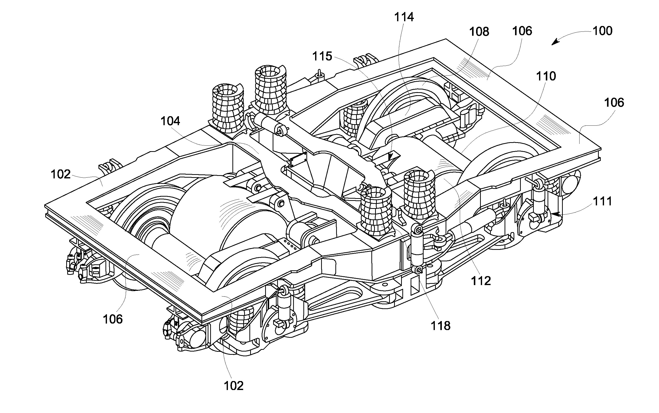
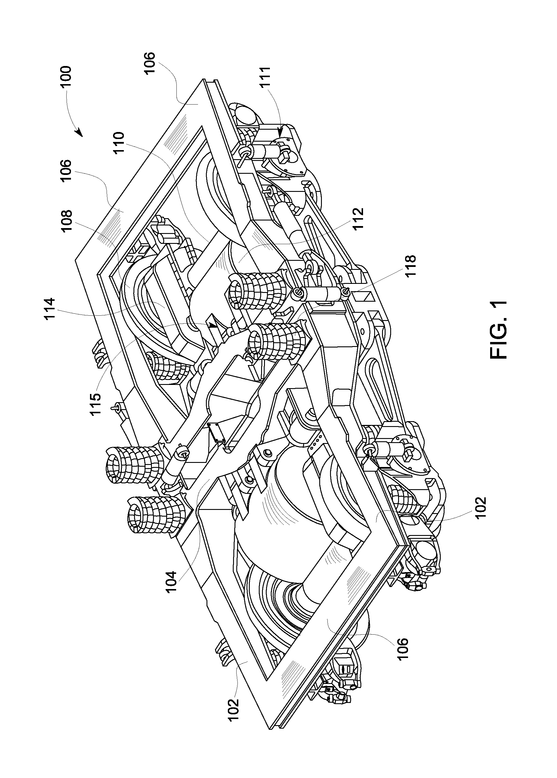
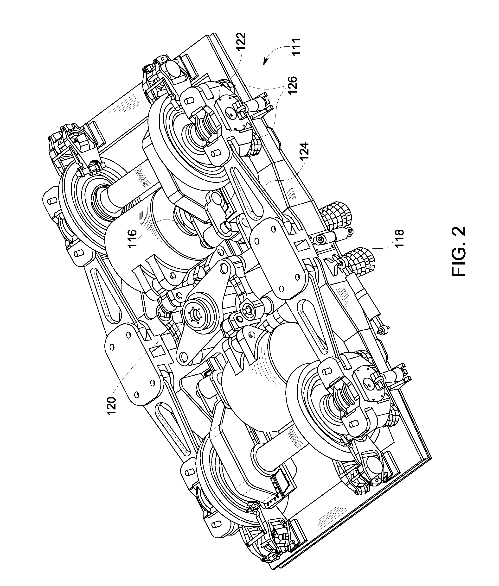
[0026]Referring to FIGS. 1-3, in the invention, a rail truck frame 100 (e.g., suitable for use in a high-speed rail vehicle) has two side members 102 that are connected at their midpoints by a transverse beam or cross member 104 (e.g., cross member may be a central cross member) and at their ends by two end members 106 to form a “B” shaped truck configuration. In other embodiments the end members may be omitted to provide an “H” shaped truck. The truck frame is supported by wheels 108 that are carried on at least one power axle 110 that extends orthogonally to, and between, the two side members 102. The power axle is suspended from the side members on axle suspensions 111. Thus, the side members and the cross member are “sprung” mass within the dynamic system of the truck frame 100. The power axle 110 is driven from a traction motor 112 via a gearbox 114. The traction motor 112 is hung from the truck frame by a motor suspension 115. Thus, relative to the wheels 108, the traction mot...

second embodiment

[0033]According to the present invention, as shown in FIG. 4, the traction motor 112 can be hung from the cross member 104 via a suspension 415. The suspension 415 includes an upper pivot 135 that connects the traction motor to the cross member 104, and also includes one or more four bar linkages 451 that connect the traction motor to the cross member. Each of the four bar linkages 451 includes links 446 that are pivotally connected at first ends to elastomeric bushings 450 mounted on pins 453 protruding from the cross member, and at second ends by pins 455 to elastomeric bushings 454 mounted in a heavy link 452, which in this embodiment is the long movable bar of the parallelogram linkage. The pins 453 and 455 collectively provide a set of second pins in addition to the pin within the upper pivot 135. As shown, the heavy link 452 may include left and right legs 452a, 452b as well as a head bracket 452c for receiving the elastomeric bushing 448.

[0034]The heavy link is pivotally conn...

third embodiment

[0035]Referring to FIG. 5, in a suspension apparatus 515 according to the present invention, the traction motor 112 is hung from the cross member 104 via an upper pivot 135. The traction motor 112 also is connected to the cross member via a coil spring piston assembly 555 that is mounted under the cross member. The coil spring piston assembly houses a spring 556 that engages a piston disc 558 mounted on a hollow shaft 560. The hollow shaft is rigidly connected with a lower bracket 548 mounted to the traction motor 112. Thus, the spring 556 may act together with the hollow shaft and the lower bracket as a biasing assembly to absorb and resist displacement of the traction motor about the upper pivot 135. Adjacent to the lower bracket, an air spring 561 provides additional resistance to swaying motions of the traction motor. Referring to FIG. 10, the piston assembly 555 for each of the traction motors 112 is horizontally offset from the other across a longitudinal midline of the truck ...


PUM


Abstract

A suspension apparatus that includes a suspension linkage connected between a traction motor and a rail vehicle truck frame at least at first and second locations. The suspension linkage including at the first location a first pin pivotally connecting the traction motor with a cross member of the truck frame, and, at the second location, at least one elastomeric element deformable to fully suspend the traction motor from the truck frame.

Description

FIELD OF THE INVENTION[0001]Embodiments of the invention relate to rail vehicles. Other embodiments relate to wheel trucks for rail vehicles and to motor suspensions for rail vehicle wheel trucks.BACKGROUND OF THE INVENTION[0002]A high-speed train car or locomotive may be supported on two trucks or bogies, each truck or bogie having two or more powered and / or non-powered axles carrying wheels. Each powered axle is driven by a motor through a gear train that includes a pinion gear driven by the traction motor shaft and driving a bull gear mounted on the axle. By way of example, a truck or bogie for use on a diesel-electric rail vehicle includes a frame, an axle mounted on the frame by journal bearings, wheels on the axle, a bull gear on the axle, and a motor and pinion gear attached to the frame. The pinion gear is operably coupled to the bull gear for the traction motor to move the pinion and thereby the bull gear, axle, and wheels. Such a system can result in disadvantageously high...

Claims


Application Information

Patent Timeline
Patent Type & Authority Applications(United States)
IPC IPC(8): B61C17/00
CPCB61C9/50
Inventor AHUJA, MUNISHWARSRIDHAR, MANDYAM RANGAYANRAGHAVAN, BRIJESH
Owner GE GLOBAL SOURCING LLC
Why Eureka
Try Eureka