Eureka AIR delivers breakthrough ideas for toughest innovation challenges, trusted by R&D personnel around the world.

UV Disinfecting Apparatus and System for Use With Contaminated Water

Inactive Publication Date: 2013-01-24
MCKINNEY JERRY L
View PDF22 Cites 7 Cited by
  • Summary
  • Abstract
  • Description
  • Claims
  • Application Information

AI Technical Summary

Benefits of technology

The present invention is about an UV disinfection apparatus for contaminated water that avoids deposits on the UV bulb. This means that the apparatus can effectively disinfect water without getting clogged or becoming less efficient over time. Additionally, the invention provides a UV disinfection system comprising a tank for contaminated water and a UV disinfectant apparatus that avoids deposition of deposits on the UV bulb. This helps to ensure consistent and efficient disinfection of water.

Problems solved by technology

However, the problem with a quartz housing or for that matter a housing over the UV bulb made of any type of UV transparent material is that over time a film of scum, particulates or the like forms on the chamber or sleeve and reduces the amount of UV radiation passing through to the point where the treated wastewater is not effectively disinfected.
In addition to treated wastewater there also exists a problem in disinfecting contaminated water from other sources.
For example, in many parts of the world while municipal water may be delivered to residential or commercial sites, the pumping systems do not produce sufficient water pressure to service all of the household needs of the numerous residences attached or connected to the municipal system.
Still another problem with municipal water in these somewhat underdeveloped locations is that the water may become contaminated due to inadequate chlorination, leaking pipes, etc.
Accordingly, even though the water is from a municipal system, it is still contaminated and can cause serious illness.
Lastly, since the water in these environments is in the holding tanks as described above and may be quiescent for undesirable periods of time, there is a chance for the growth of microorganisms, bacteria and the like which would again contaminate the water prior to use.

Method used


Image

  • UV Disinfecting Apparatus and System for Use With Contaminated Water
  • UV Disinfecting Apparatus and System for Use With Contaminated Water
  • UV Disinfecting Apparatus and System for Use With Contaminated Water

Examples


Embodiment Construction

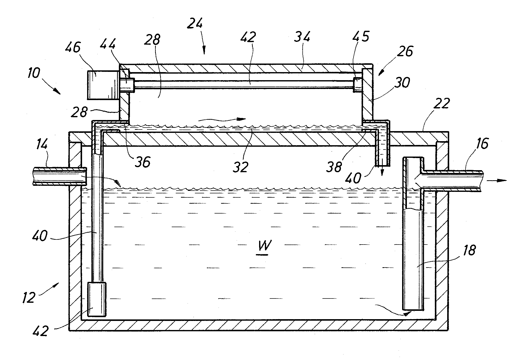
[0026]As used herein, the term “treated wastewater” generally refers to wastewater from a septic system which has been subjected to a pretreatment or settling tank to remove large solids and aerobic digestion to produce substantially clarified, treated wastewater. The term “contaminated water” refers to treated wastewater as well as water from other sources which is intended to be used as potable water or at the very least relatively bacteria and microorganism free water. Thus, in the description which follows, treated wastewater and contaminated water may be used inter-changeably.

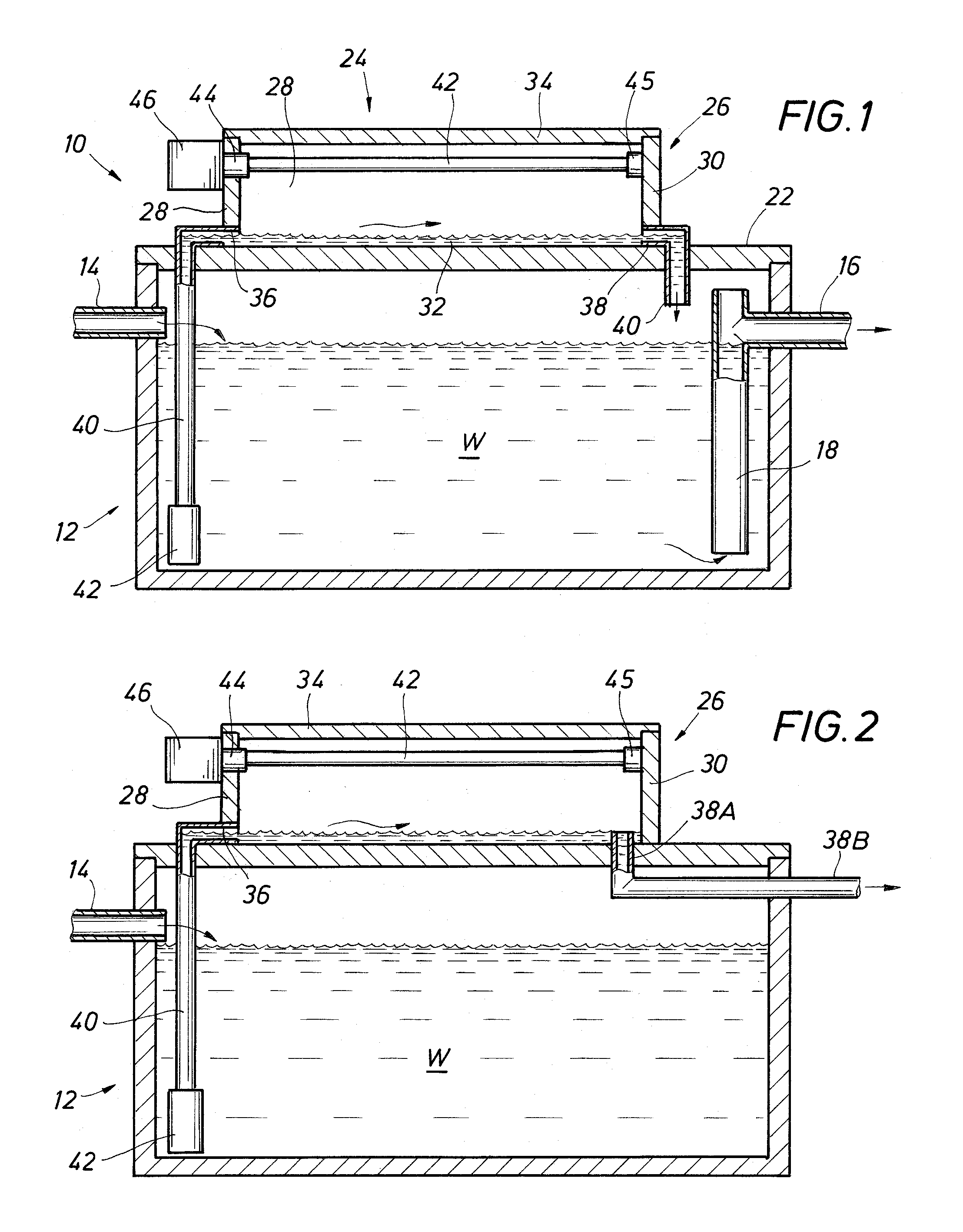
[0027]Referring to FIG. 1, there is shown an embodiment of the UV disinfectant system, indicated generally as 10. The embodiment shown in FIG. 1 comprises a tank 12 having a volume W of treated wastewater therein. Tank 12 has an inlet 14 and an outlet 16, inlet 14 being connected to a source of clarified treated wastewater from a packaged plant, outlet 16 being connected to a riser pipe 18 extending into t...


PUM


Abstract

An apparatus for disinfecting contaminated water having a body forming a flow channel with a first end and a second end flowing generally from said first end of the flow channel to an outlet for removing contaminated water from the flow channel. There is a mount for suspending a UV bulb assembly above the channel at a distance above but sufficiently close to the level of contaminated water in the channel to effect UV radiation of contaminated water in the channel.

Description

FIELD OF THE INVENTION[0001]The present invention relates to disinfecting contaminated water and, more specifically, disinfecting contaminated water using ultraviolet radiation.BACKGROUND OF THE INVENTION[0002]Many homes and small businesses, particularly in rural and outlying areas which are not connected to rural treatment systems rely on septic tank systems, aerobic treatment systems, small package plants or other types of local treatment apparatus (collectively “packaged plants”) for wastewater treatment. These packaged plants generally use one or more tanks containing the treatment apparatus connected to a field drip system or drain field for ultimate disposal of the treated waters. Treatment entails degradation of waste in the water by the biological processes of bacteria and microorganisms. This “treated wastewater” generally contains bacteria and other microorganisms.[0003]The fluid quality produced by packaged plants is usually regulated by one or more governmental agencies...

Claims


Application Information

Patent Timeline
IPC IPC(8): A61L2/10
CPCC02F2201/3221C02F1/325Y02W10/33Y02W10/37
Inventor MCKINNEY, JERRY L.
Owner MCKINNEY JERRY L
Why Eureka
Eureka Blog
Learn More