Rotational electric machine and method for manufacturing retaining ring for the same

a technology of rotating electric machines and retaining rings, which is applied in the direction of dynamo-electric machines, electrical apparatus, magnetic circuit shapes/forms/construction, etc., can solve the problems of ring and core array size varies, magnetic steel sheets are easily buckled by surface pressure applied to the outer circumferential surface,

Inactive Publication Date: 2013-01-24
AISIN SEIKI KK
View PDF4 Cites 6 Cited by
  • Summary
  • Abstract
  • Description
  • Claims
  • Application Information

AI Technical Summary

Problems solved by technology

However, the size of each component of the rotational electric machine varies and the above-mentioned interference varies depending on the dimension differences.
However, in the case that the interference between the cooled retaining ring and the core array is still great even when the shrink fitting is applied, as is the case in the press fitting, the magnetic steel sheets are easily buckled by the surface pressure applied to the outer circumferential surface.

Method used


Image

  • Rotational electric machine and method for manufacturing retaining ring for the same
  • Rotational electric machine and method for manufacturing retaining ring for the same
  • Rotational electric machine and method for manufacturing retaining ring for the same

Examples


Embodiment Construction

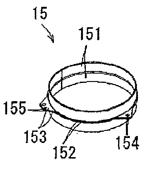
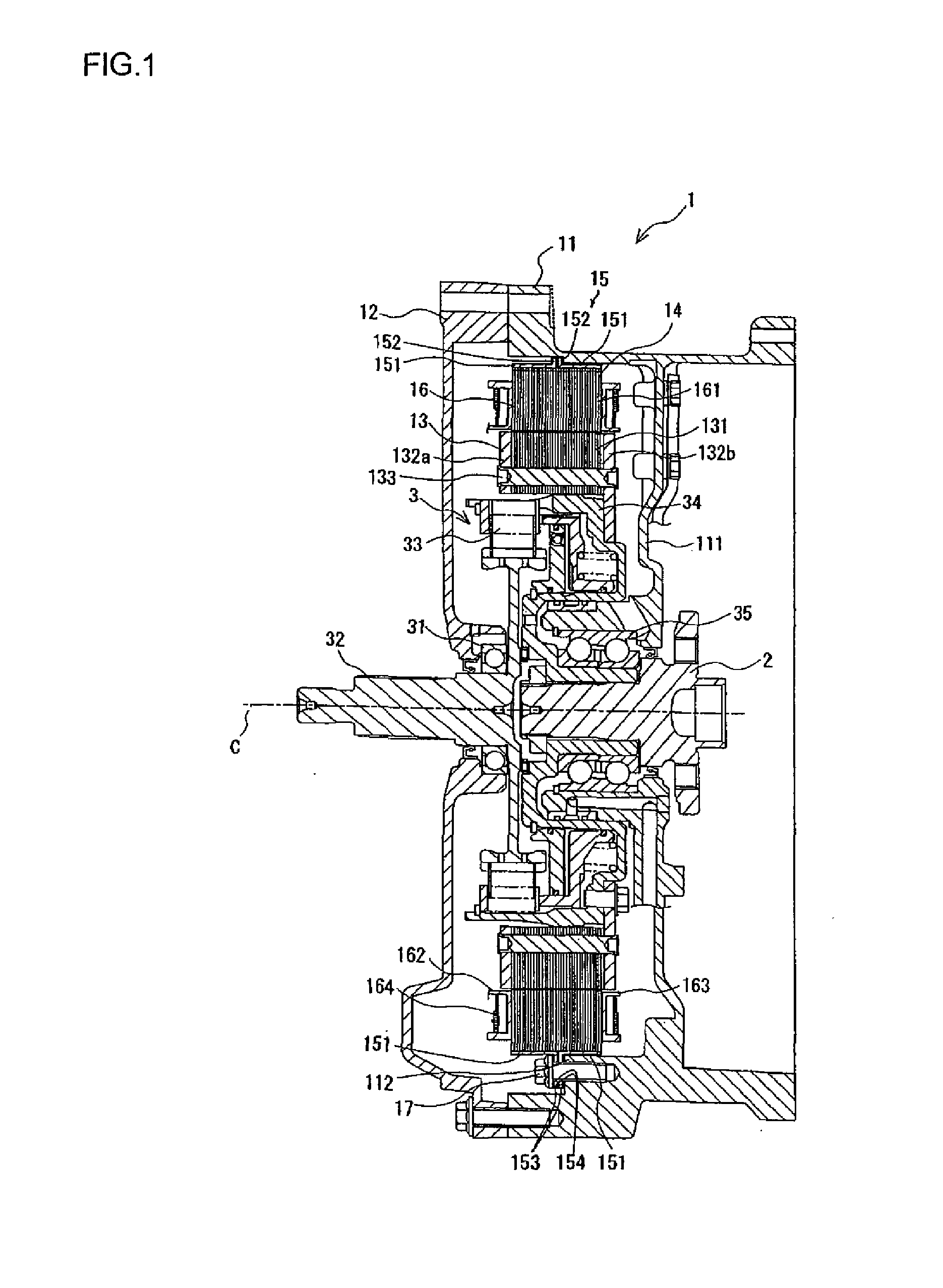
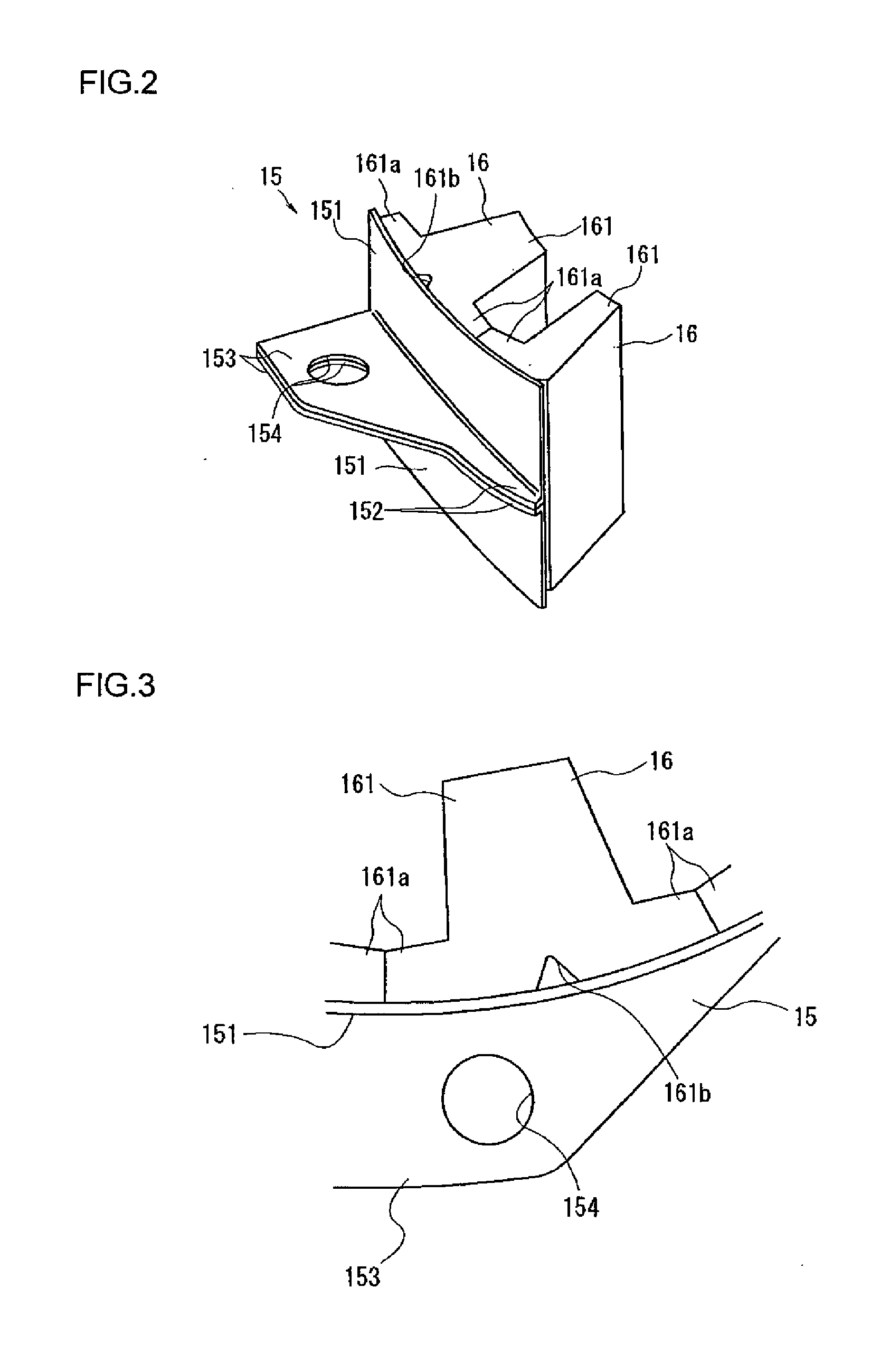
[0033]An embodiment of the rotational electric machine according to the invention will be explained with reference to FIG. 1 to FIG. 4. The rotational electric machine 1 is a synchronous motor for driving wheels of a hybrid vehicle. The left side in FIG. 1 is referred to as the front side of the rotational electric machine 1 and a clutch device 3, and the right side is referred to as the rear side thereof. However, the directions do not have any relations to the actual directions relative to the vehicle. Additionally, a rotation axis direction and an axial direction used in the explanation denote a direction extending along a rotation axis C of the rotational electric machine 1, in other words, the left and right directions in FIG. 1 unless otherwise mentioned. Bobbins 162, 163 and a coil 164 of a core 16 are omitted in FIG. 2 and FIG. 3.

[0034]As shown in FIG. 1, a motor housing 11 (which corresponds to a housing of the invention) is sealed by a motor cover 12 at the front portion o...


PUM

PropertyMeasurementUnit
surface pressureaaaaaaaaaa
thicknessaaaaaaaaaa
outer diameteraaaaaaaaaa

Abstract

A rotational electric machine comprises a stator having a plurality of cores arranged in an annular ring shape and a retaining ring capable of retaining the plurality of cores on an inner circumferential surface so that a surface pressure is applied to an outer circumferential surface of the plurality of cores. The rotational electric machine further comprises a rotor provided radially inside of the stator facing the plurality of cores in a radial direction and rotatable relative to the stator. The stator and the rotor are mounted on a housing. The retaining ring is provided with a flange portion. The flange portion is formed on an axial middle portion of an outer circumferential surface of the retaining ring and to be attachable to the housing.

Description

TECHNICAL FIELD[0001]This invention relates to a rotational electric machine, which drives a rotor in response to energization of a core of a stator, and a method for manufacturing a retaining ring retaining the core.BACKGROUND OF THE TECHNOLOGY[0002]For example, the patent document 1 discloses a known technology relating to a rotational electric machine having a stator formed in such a way that plural cores, each of which is wound with a coil, are retained in the form of an annular shape on an inner circumferential surface of a retaining ring, and a rotor formed to face the stator in a radial direction thereof. The known technology above is generally used as a motor for driving wheels of a hybrid vehicle. According to the patent document 1, the plural cores arranged in the annular shape are fixed on the retaining ring, and then an attachment flange portion provided at an end portion of the retaining ring in a rotation axis direction (hereinafter referred to, simply as an axial dire...

Claims


Application Information

Patent Timeline
Patent Type & Authority Applications(United States)
IPC IPC(8): H02K1/18H02K15/00
CPCH02K1/185Y10T29/49009H02K7/14
Inventor SATO, TOMOHIRO
Owner AISIN SEIKI KK
Why Eureka
Try Eureka