Vehicle-body front structure of vehicle

a front structure and vehicle technology, applied in the direction of vehicle components, superstructure subunits, bumpers, etc., can solve the problems of preventing collision energy from reaching a higher level

Active Publication Date: 2016-05-03
MAZDA MOTOR CORP
View PDF16 Cites 5 Cited by
  • Summary
  • Abstract
  • Description
  • Claims
  • Application Information

AI Technical Summary

Benefits of technology

[0006]The present invention has been devised in view of the above-described matters, and an object of the present invention is to provide a vehicle-body front structure of a vehicle which can properly achieve the sufficient energy absorption in the collision and the prompt flicking-up of the obstacle, preventing the obstacle from coming in below the vehicle-body front portion.
[0008]According to the present invention, in a first stage from a collision start of the vehicle's colliding with a front obstacle, the obstacle can be properly prevented from coming in below the vehicle-body front portion by means of the supporting function of the brackets and the stiffener (in a high-rigidity state). Further, in a second stage subsequent from the first stage, since the front end portion of the stiffener slants downward and forward and has the open cross section, the stiffener deforms in such a manner that it slants downward and rearward, thereby becoming in a low-rigidity state, so that collision energy can be properly absorbed. Then, in a third stage after the second stage, since the stiffener which has deformed is substantially aligned with the brackets extending obliquely downward and forward, the stiffener generates a large resistant force (a high rigidity), cooperating with the brackets, so that it can properly perform the function of flicking the obstacle up. Particularly, in a vehicle not having any portion which collides at a sufficiently-higher level than a knee portion of a pedestrian, for example, the energy absorption can be achieved sufficiently and also the protection of the pedestrian can be properly improved.
[0009]According to an embodiment of the present invention, a portion of the stiffener around an attachment portion of the stiffener to the bracket has an open cross section over an entire longitudinal length thereof. In this embodiment, it can be prevented that the rigidity of connection portions of the stiffener to the brackets becomes too high locally, so that the above-described effects of the present invention can be obtained surely.
[0011]According to another embodiment of the present invention, the brackets and the stiffener are configured such that a load / deformation characteristic showing a relationship of a collision load and a deformation amount which is obtained thereby in a head-on collision shows three-stage changes which are comprised of a first stage from a collision start, a second stage after the first stage, and a third stage after the second stage, an increasing ratio of the deformation amount relative to the collision load in the second stage being set to be greater than that in the first stage or the third stage. In this embodiment, the specific load / deformation characteristic by the brackets and the stiffener is provided preferably, so that the above-described effects of the present invention can be obtained surely.
[0012]According to another embodiment of the present invention, an energy absorbing member extending in the vehicle width direction is attached to a front face of the bumper beam, and a front end of an engine hood or a front end of a front vehicle-body exterior member which is substantially flatly continuous from the front end of the engine hood is positioned in front of the energy absorbing member. In this embodiment, in a vehicle in which the front end of the engine hood or the front end of the front vehicle-body exterior member which is substantially flatly continuous from the front end of the engine hood is located at a considerably low level, the above-described effects can be obtained. Further, when the obstacle is flicked up in the third stage, a lower portion of the obstacle which is located below the front end of the engine hood or the front end of the front vehicle-body exterior member can be properly flicked up by utilizing the above-described front ends as a fulcrum, so that the obstacle can be properly flicked up onto the engine hood and thereby the protection of the obstacle can be achieved surely.

Problems solved by technology

Meanwhile, in a vehicle, such as a sports car, in which the level of a front end of the engine hood (or a front end of a vehicle-body exterior member positioned in front of the engine hood) is considerably low, it may be difficult to absorb the collision energy at a higher level than the knee of the leg portion of the pedestrian as the obstacle, for example.
According to the protecting member of the above-described patent document, however, it may be difficult to obtain both the energy absorption sufficient for the partial deformation restraint of the obstacle and the flicking-up of the obstacle by means of the protecting member only.
Especially, since a load / deformation characteristic showing a relationship of a collision load and a deformation amount of the protecting member of the above-described patent document is configured such that the deformation amount increases substantially proportionally to an increase of the collision load, it may be difficult to satisfy both the sufficient energy absorption in the collision and the flicking-up of the obstacle by means of the protecting member only.

Method used


Image

  • Vehicle-body front structure of vehicle
  • Vehicle-body front structure of vehicle
  • Vehicle-body front structure of vehicle

Examples


Embodiment Construction

[0023]Hereinafter, a preferred embodiment of the present invention will be described referring to the accompanying drawings.

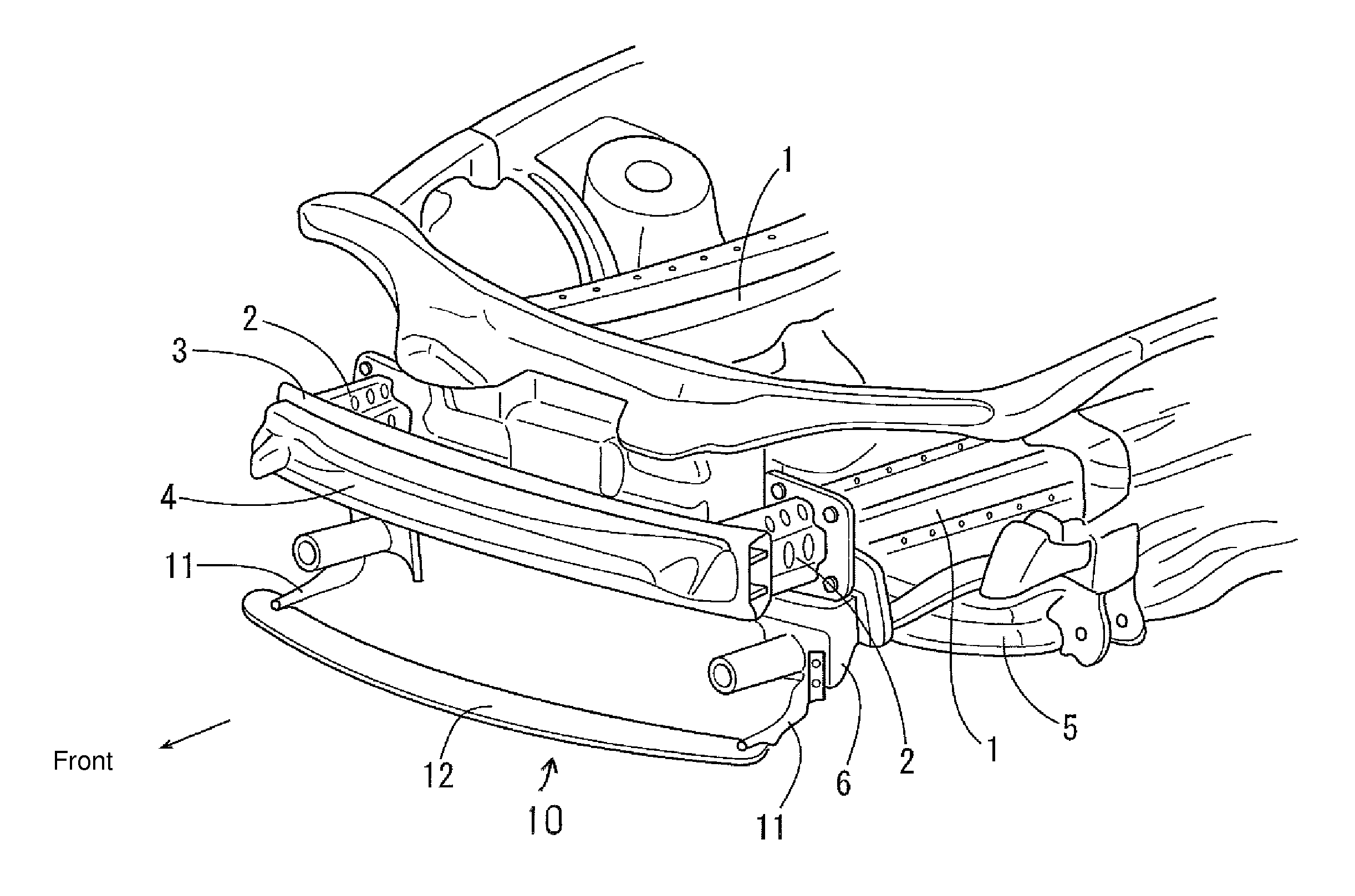
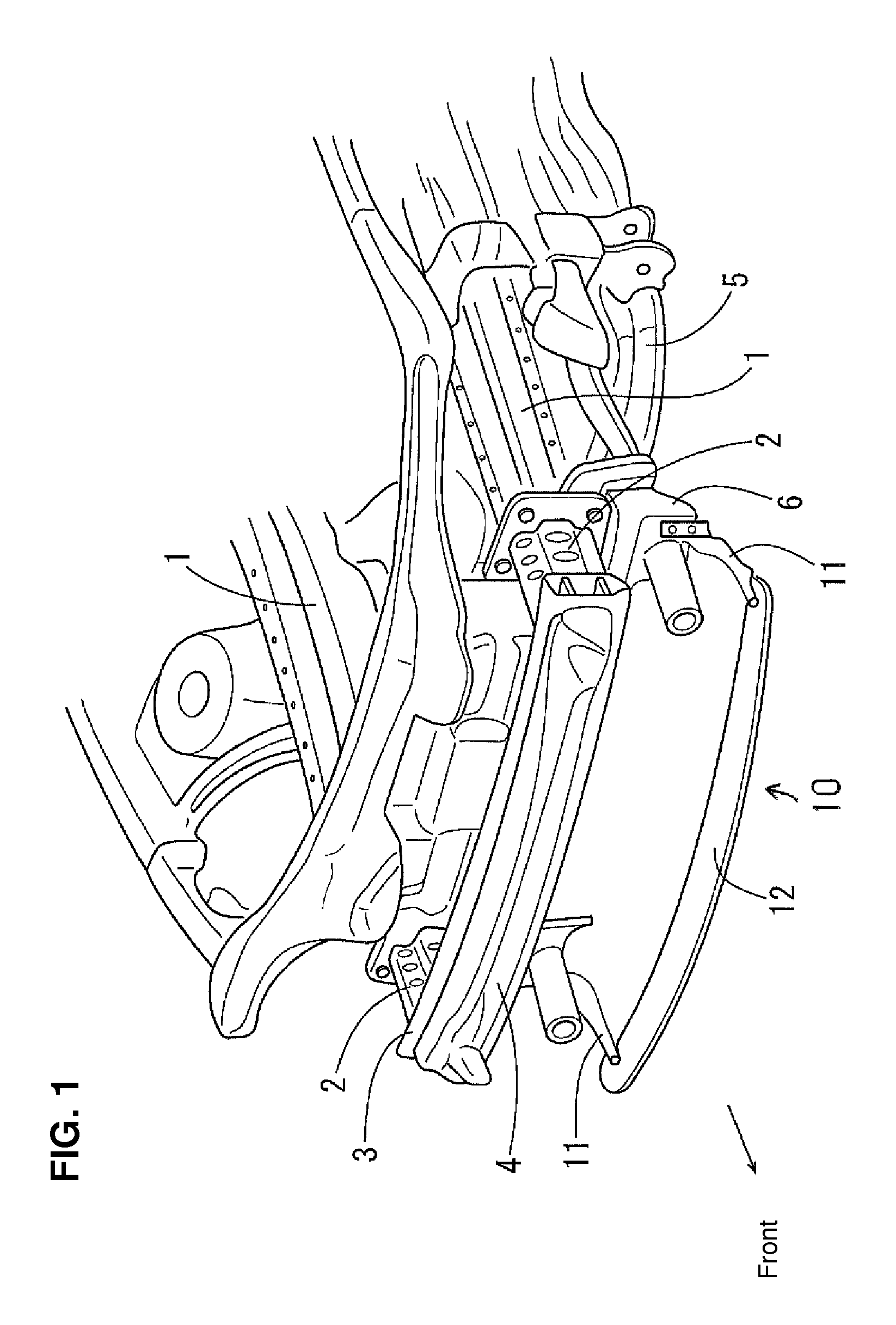
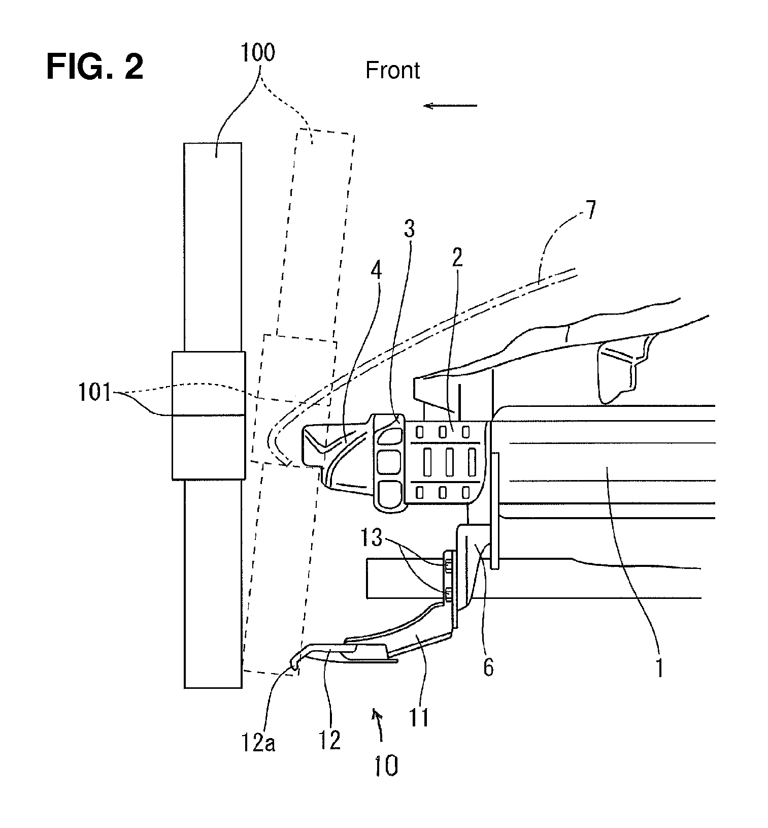
[0024]In FIG. 1 showing a front structure of a vehicle, reference character 1 denotes side frames (front side frames) as vehicle-body reinforcing members extending longitudinally. A crash can 2 is attached to a front end of each of the side frames 1. A bumper beam 3 as a reinforcing member extending in a vehicle with direction is attached to a pair of right-and-left crash cans 2. An energy absorbing member 4 which extends in the vehicle width direction is attached to a front face of the bumper beam 3. The energy absorbing member 4 is made from synthetic resin, for example. In FIG. 1, reference character 5 denotes a suspension cross member (suspension frame).

[0025]A protecting member 10 which is comprised of brackets 11 and a stiffener (lower bumper beam) 12 is attached to front end portions of the side frame 1 via setting plates 6 as reinforcing members. The br...


PUM


Abstract

A pair of right-and-left brackets which extend obliquely downward and forward from respective front portions of a pair of right-and-left side frames are provided. A stiffener which extends in a vehicle width direction below a bumper beam is attached to respective front ends of the pair of right-and-left brackets. The stiffener is configured such that its front end portion slants downward and forward and has an open cross section, and its rear end portion thereof has a closed cross section. An obstacle can be prevented from coming in below a vehicle-body front portion, and also the sufficient energy absorption in a collision and the prompt flicking-up of an obstacle can properly achieved.

Description

BACKGROUND OF THE INVENTION[0001]The present invention relates to a vehicle-body front structure of a vehicle.[0002]An automotive vehicle, as a vehicle, comprises a pair of right-and-left side frames extending longitudinally at a vehicle-body front portion and a bumper beam extending in a vehicle width direction and attached to respective front ends of the pair of right-and-left side frames. Further, the automotive vehicle may be equipped with a protecting member including a stiffener (which may be called a lower bumper beam) extending in the vehicle width direction which is provided below the bumper beam in order that when a vehicle collides with a front obstacle, especially when a pedestrian's leg portion hits, the obstacle is restrained from coming in below the vehicle-body front portion. As the above-described protecting member, a structure which can effectively absorb collision energy (impact) in the collision with a properly short stroke is disclosed in Japanese Patent Laid-Op...

Claims


Application Information

Patent Timeline
Patent Type & Authority Patents(United States)
IPC IPC(8): B60J9/00B60R19/12B62D25/08B60R21/34B60R21/00
CPCB60R21/34B60R19/12B62D25/08B60R2021/002B60R2021/0004B60R2021/0037B60R2021/0053B60R2021/343
Inventor KITO, MASATOKISOGABE, HIROSHITAKADA, HIROFUMIWATANABE, TSUTOMUFURUMOTO, ARIHIROMURAKAMI, RYUMANAKAMAE, TAKAYUKI
Owner MAZDA MOTOR CORP
Why Eureka
Try Eureka