[0011] Further, with the above elastic wheel, the belt is preferred to be a
steel belt formed by burying steel cords in rubber. In particular, an introduction angle of the
steel belt is preferred to be substantially a right angle with respect to the wheel circumferential direction. In this way, it is possible to exactly obtain the aforesaid
advantage of the present invention, particularly to increase the spring rigidity ratio in the axial direction.
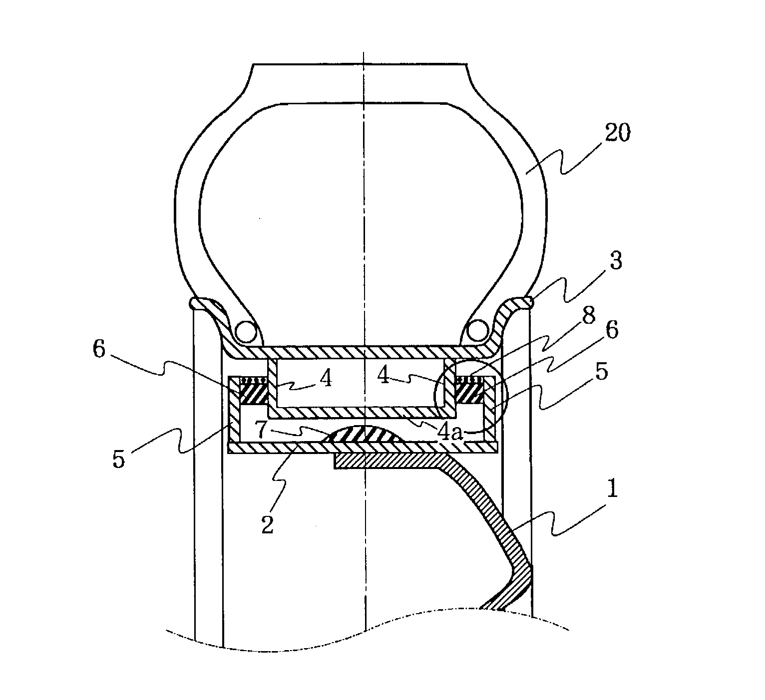
[0012] Furthermore, according to the present invention, there is provided an elastic wheel comprising a disk, a rim supporting a tire, a pair of guides annularly fixed on the inner periphery surface of the rim, a pair of walls annularly fixed in two side areas along the wheel axial direction on the outer periphery surface of a base rim disposed on the disk or on the outer periphery surface of the disk, and rubber elastic bodies annularly interposed between the side faces of the guides and the side faces of the walls, wherein one or both of the side faces on which the rubber elastic bodies are fixed have uneven portions.
[0013] Using the above arrangement, it is possible to absorb vibration by virtue of shear deformation of the installed rubber elastic bodies, particularly to improve the riding quality, the vibration prevention performance and the sound insulation performance when there is a
low input. As for sound insulation performance, the elastic wheel is extremely effective for sound insulation in
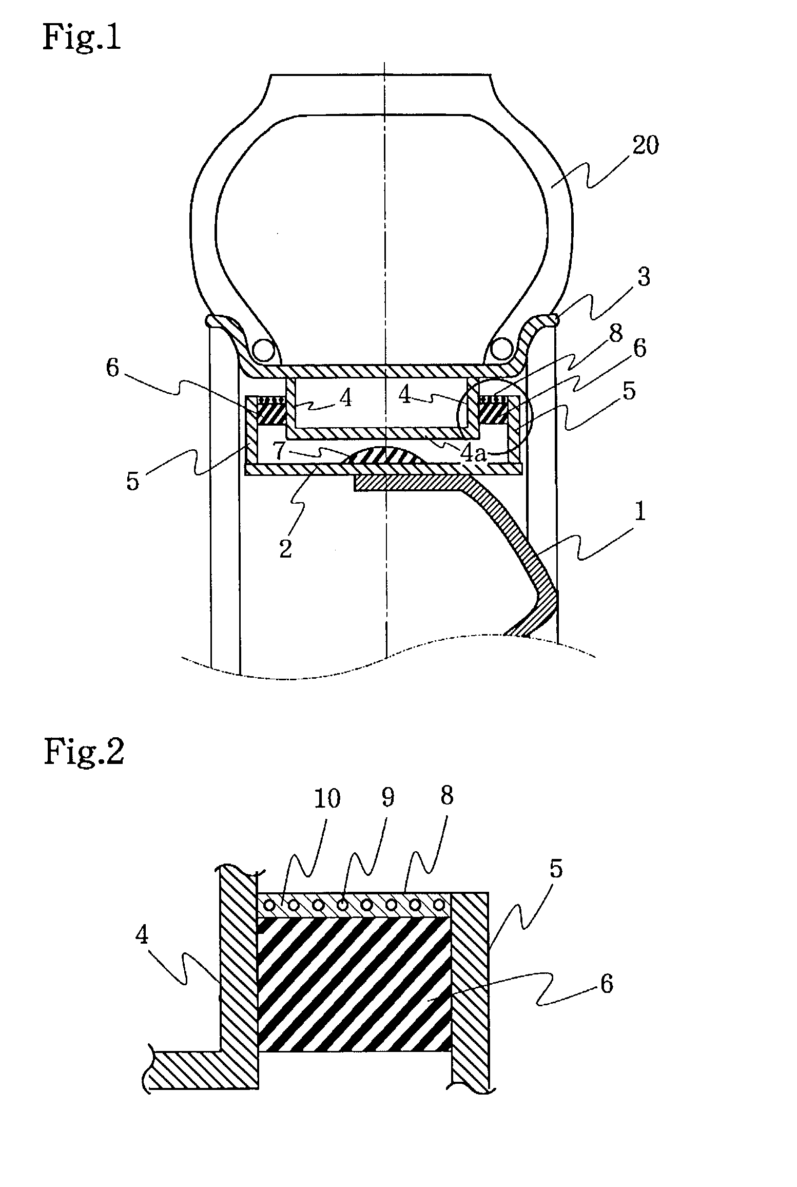
high frequency renges of 100 Hz or more. Further, since uneven portions are formed on the surfaces on which rubber elastic bodies are fixed, an entire bonding area can be increased. Therefore, as compared with an example in which rubber elastic body bonding surfaces are flat, it is allowed to more firmly fix the rubber elastic bodies and to increase a wheel
torsional rigidity, thus improving a steering stability.
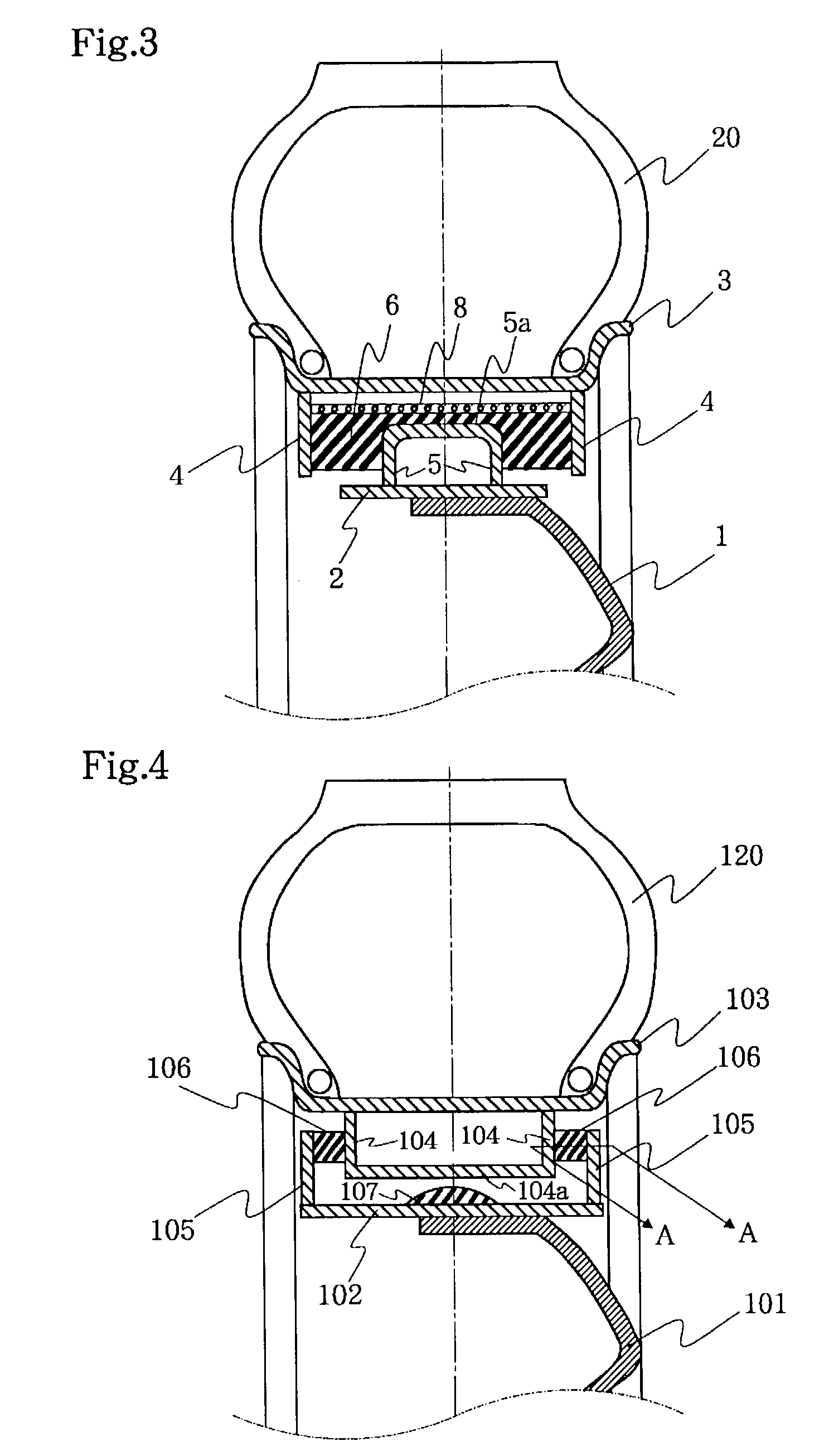
[0014] Here, the aforesaid uneven portions are preferred to be in a corrugated form. In this way, it is possible to exactly obtain the aforesaid effects, without bringing about any damage to the guides with which the rubber elastic bodies are fixed, and without damaging the strength of the walls. Moreover, it is possible to inhibit a rigidity rising in the vertical direction of the wheel and to maintain good sound insulation performance and good riding quality. Further, it is preferable that the aforesaid uneven portions be formed on both of every two mutually facing side faces on which the rubber elastic bodies are to be fixed, and that uneven portions formed on every two mutually facing side faces be complementary to each other. Therefore, it is possible to more exactly affect a shear deformation of the rubber elastic bodies and thus more exactly obtain the aforesaid advantages. In addition, it is possible to reduce the rigidity in the wheel vertical direction and to ensure a uniform rigidity in the wheel circumferential direction. Moreover, with the above-descried elastic wheel, the width between the pair of guides in the wheel axial direction is narrower than the width between the pair of walls in the wheel axial direction, the inner end portions of the pair of guides in the wheel radial direction are combined with each other so as to form a substantially U-shaped cross section in the wheel axial direction, a rubber elastic body is annularly interposed between the inner periphery surface of the substantially U-shaped guide
assembly and the disk or the outer periphery surface of the base rim, in a manner such that a gap is formed between the rubber elastic body and one of said periphery surfaces. Alternatively, the width between the pair of guides in the wheel axial direction is larger than the width between the pair of walls in the wheel axial direction, the outer end portions of the pair of guides in the wheel radial direction are combined with each other so as to form an inverted substantially U-shaped cross section in the wheel axial direction, a rubber elastic body is annularly interposed between the outer periphery surface of the inverted substantially U-shaped guide
assembly and the inner periphery surface of the rim, in a manner such that a gap is formed between the rubber elastic body and one of said periphery surfaces. In this way, it is possible to exactly obtain the aforesaid effects and to prevent some significant deformation possibly caused by a
high input, by virtue of a compressing action produced by the rubber elastic bodies disposed on the outer periphery surface of the base rim or on the inner periphery surface of the rim.
[0015] Furthermore, according to the present invention, there is provided an elastic wheel comprising a disk, a rim supporting a tire, a pair of guides annularly fixed on the inner periphery surface of the rim, a pair of walls annularly fixed in two side areas along the wheel axial direction on the outer periphery surface of a base rim disposed on the disk or on the outer periphery surface of the disk, and rubber elastic bodies annularly interposed between the side faces of the guides and the side faces of the walls, wherein the width between the pair of guides in the wheel axial direction is narrower than the width between the pair of walls in the wheel axial direction, the inner end portions of the pair of guides in the wheel radial direction are combined with each other so as to form a substantially U-shaped cross section in the wheel axial direction, a rubber elastic body is annularly disposed on the inner periphery surface of the substantially U-shaped guide
assembly in a manner such that a gap is formed between the rubber elastic body and the disk or the outer periphery surface of the base rim, and is integrally formed with the rubber elastic bodies annularly interposed between the side faces of the guides and the side faces of the walls. In particular, a spring is wound within the integrally formed rubber elastic body along the wheel circumferential direction. Alternatively, there is provided an elastic wheel comprising a disk, a rim supporting a tire, a pair of walls annularly fixed on the outer periphery surface of a base rim disposed on the disk or on the outer periphery surface of the disk, a pair of guides annularly fixed in two side areas along the wheel axial direction on the inner periphery surface of the rim, and rubber elastic bodies annularly interposed between the side faces of the guides and the side faces of the walls, wherein the width between the pair of guides in the wheel axial direction is larger than the width between the pair of walls in the wheel axial direction, the outer end portions of the pair of walls in the wheel radial direction are combined with each other so as to form an inverted substantially U-shaped cross section in the wheel axial direction, a rubber elastic body is annularly disposed on the outer periphery surface of the inverted substantially U-shaped guide assembly in a manner such that a gap is formed between the rubber elastic body and the inner periphery surface of the rim, and is integrally formed with the rubber elastic bodies annularly interposed between the side faces of the guides and the side faces of the walls. In particular, a spring is wound within the integrally formed rubber elastic body in the wheel circumferential direction.
[0016] By virtue of the above arrangement, it is possible to absorb vibration by virtue of shear deformation of the installed rubber elastic bodies, particularly to improve the riding quality, the vibration prevention performance and the sound insulation performance when there is a low input. Meanwhile, by virtue of an action of the spring imbedded in the rubber elastic bodies, it is possible to provide a higher wheel rigidity in the lateral and circumferential directions than in the vertical direction, thereby improving the steering stability. Further, as for sound insulation performance, the elastic wheel is extremely effective for sound insulation in
high frequency ranges of 100 Hz or more.

