Uncoupling system for an aircraft turbojet engine rotary shaft

Active Publication Date: 2013-01-24
SN DETUDE & DE CONSTR DE MOTEURS DAVIATION S N E C M A
View PDF5 Cites 26 Cited by
  • Summary
  • Abstract
  • Description
  • Claims
  • Application Information

AI Technical Summary

Benefits of technology

[0008]A main object of the present invention is thus to mitigate such drawbacks by proposing a decoupling system for a rotary shaft that makes it possible, while using only a

Problems solved by technology

In such a turbojet, the breaking of a fan blade (e.g. as a result of ingesting a bird) gives rise to an unbalance on the low-pressure shaft in the plane of the fan.
In such a situation, large loads associated with the resulting unbalance are transmitted to the structures of the turbojet, firstly via the bearing 1 that supports the shaft close to the fan, and secondly as a result of contacts between the fan blades and the casing that surrounds them.
That gives rise to significant bending of the low-pressure shaft under the high-p

Method used


Image

  • Uncoupling system for an aircraft turbojet engine rotary shaft
  • Uncoupling system for an aircraft turbojet engine rotary shaft
  • Uncoupling system for an aircraft turbojet engine rotary shaft

Examples


first embodiment

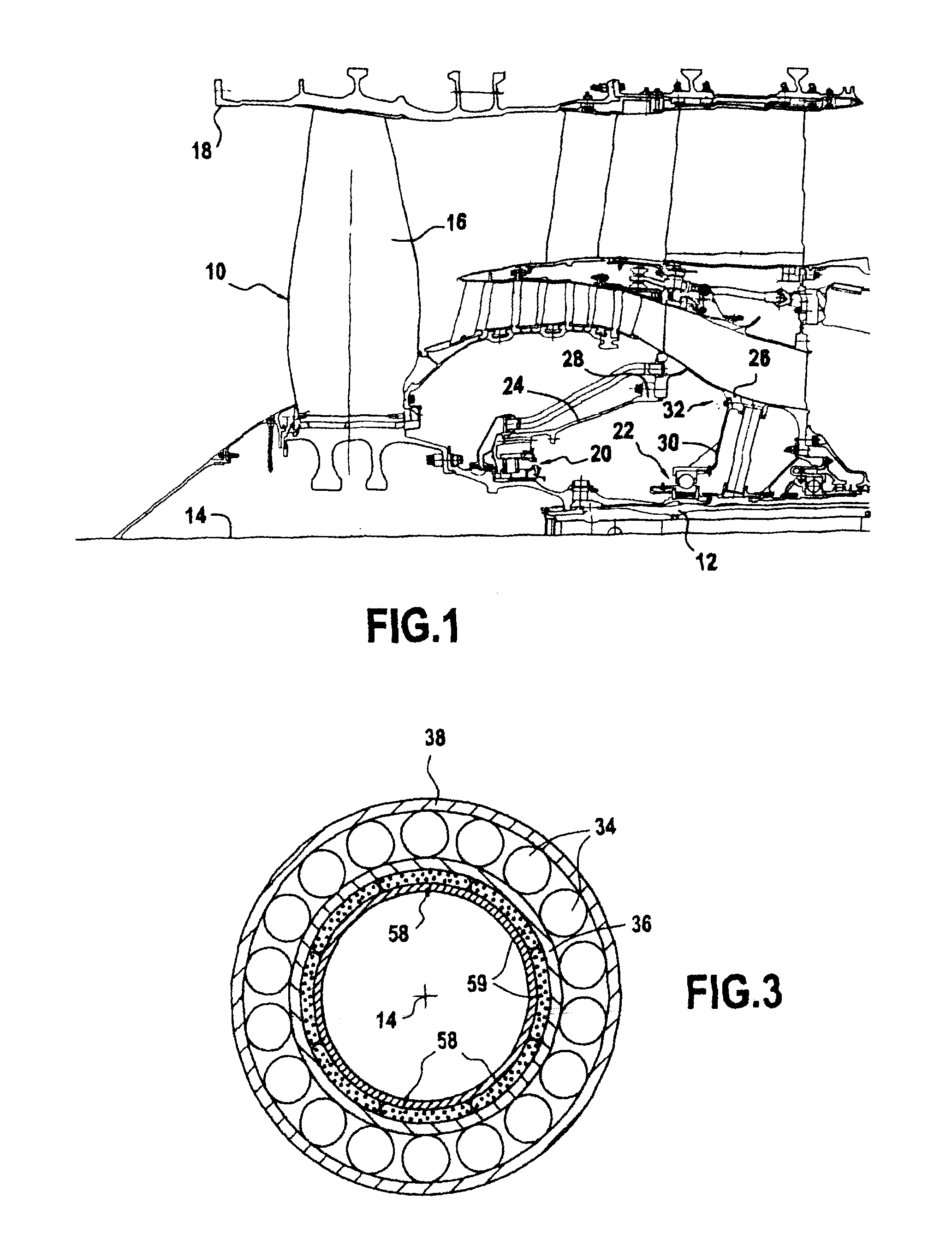
[0028]There follows initially a description of such a decoupling system, given with reference to FIGS. 2 and 3.

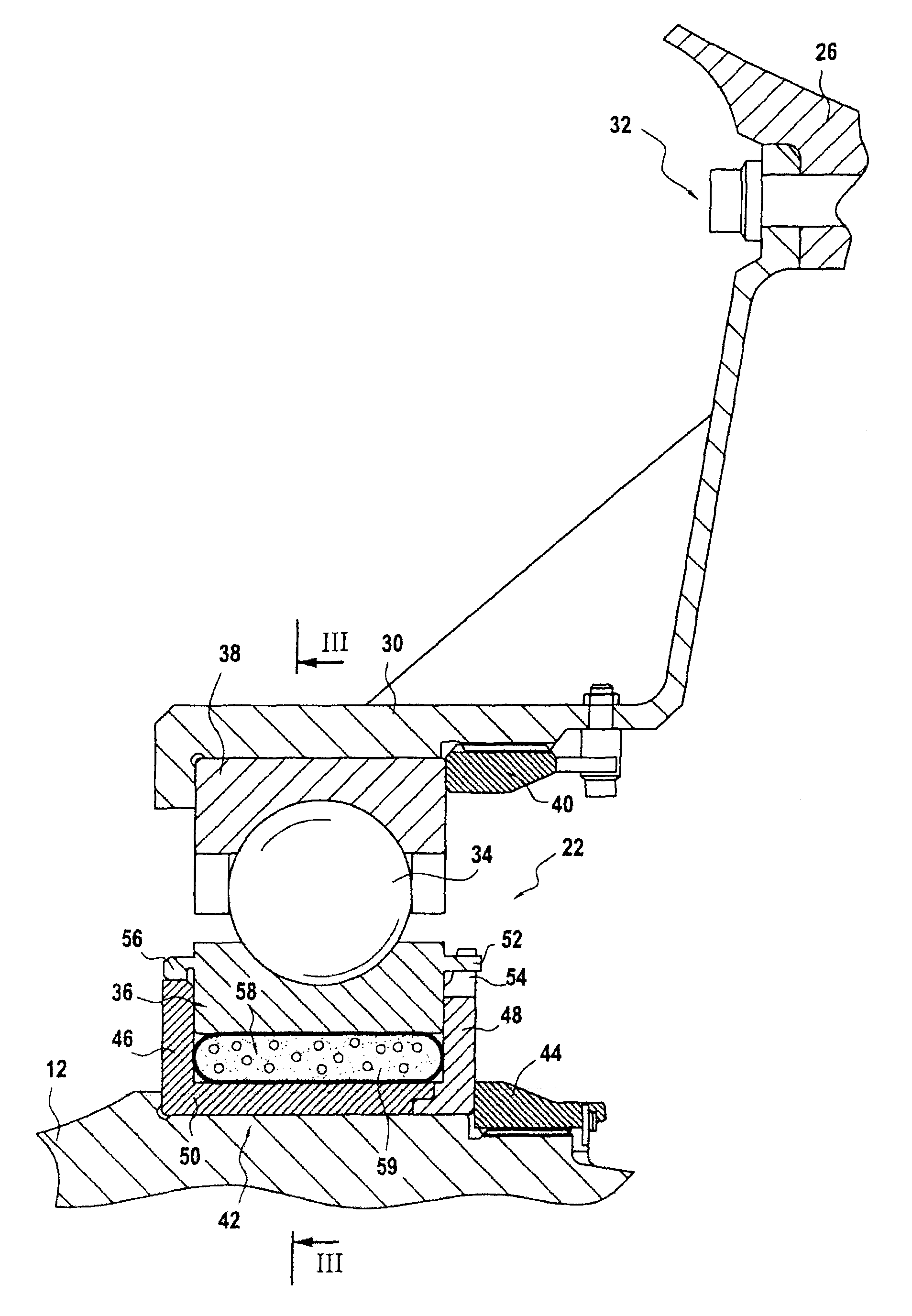
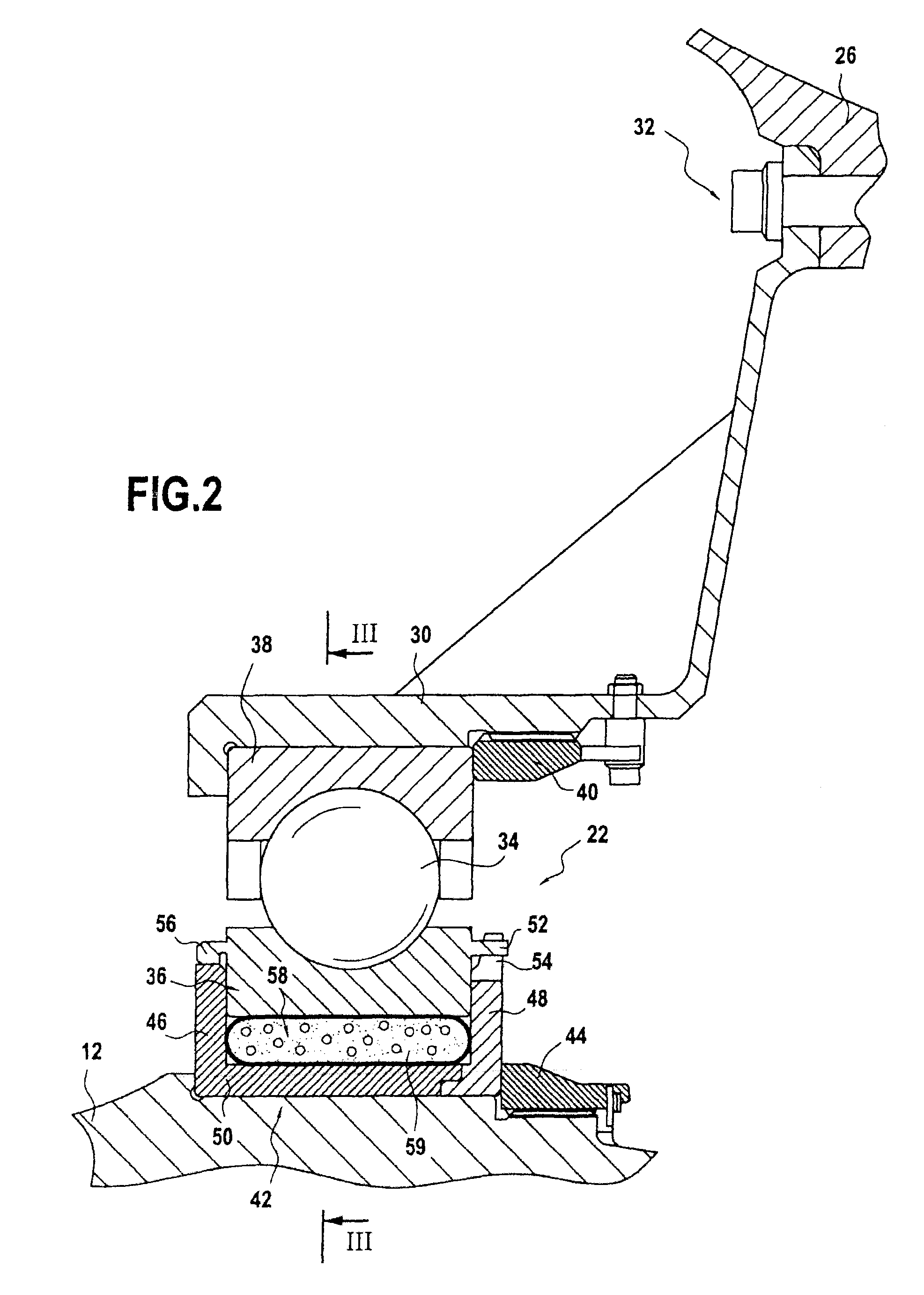
[0029]The rear bearing 22 has a plurality of balls 34 that are inserted between an inner ring 36 arranged beside the low-pressure shaft 12 and an outer ring 38 arranged beside the rear bearing support 30, these rings defining raceways for the balls. More precisely, the outer ring is fastened to the rear bearing support 30 by means of a nut 40.

[0030]The inner ring is mounted in an annular mounting chamber 42 that is an interference fit on the low-pressure shaft and that is axially fastened thereon by a nut 44. The mounting chamber 42 presents an upstream wall 46 that is axially spaced apart from a downstream wall 48 by a bottom wall 50.

[0031]In order to enable rotary torque to be transmitted from the low-pressure shaft to the inner ring of the rear bearing, the ring includes a plurality of lugs 52 co-operating with corresponding teeth 54 formed at the free end of the downstr...

second embodiment

[0042]This second embodiment differs from the first in particular in that the inner ring 36′ of the rear bearing 22′ has a flange 60 that extends axially upstream and that is fastened to a corresponding flange 62 of the mounting chamber 42′ (this flange 62 extends axially upstream from the end of the upstream wall 46′ of the mounting chamber). These flanges 60 and 62 are fastened to each other by means of a nut-and-bolt system 64 and they form a flexible connection system that allows the inner ring to move radially relative to the mounting chamber. This flexible connection 60, 62 also enables the inner ring to be centered radially on the mounting chamber and to take up the axial forces generated by the thrust.

[0043]In this second embodiment, since no mechanical breakage occurs in the connection between the inner ring and the mounting chamber in the event of a fan blade being lost, it is necessary to take account of the flexibility of the connection 60, 62 when determining the charac...


PUM


Abstract

A decoupling system for a rotary shaft of an aircraft turbojet, the decoupling system including: a rolling bearing including rolling elements inserted between a first ring fastened to a stationary bearing support and a second ring mounted in a mounting chamber fastened to a rotary shaft; a transmission mechanism transmitting rotary torque from the rotary shaft to the second ring; a mechanism allowing the second ring to move radially relative to the mounting chamber when a static force associated with an unbalance affecting the rotary shaft exceeds a predetermined threshold; and a plurality of leaktight flexible bags interposed between the second ring and the mounting chamber and each including a heterogeneous structure including a porous capillary solid matrix and an associated liquid relative to which the matrix is lyophobic.

Description

BACKGROUND OF THE INVENTION[0001]The present invention relates to a rotary shaft of an aircraft turbojet, which shaft is supported in rotation by rolling bearings. The invention relates more particularly to a system enabling such a rotary shaft to be decoupled in the event of it being subjected to a large unbalance.[0002]A two-spool bypass turbojet has two rotors, namely a low-pressure rotor and a high-pressure rotor, which rotors are supported by rolling bearings. Typically, the low-pressure rotor is supported by two rolling bearings at the front (referred to herein as “bearing 1” and “bearing 2”) and by a rolling bearing at the rear. These bearings need to be able to withstand the axial and radial loads of the turbojet.[0003]In such a turbojet, the breaking of a fan blade (e.g. as a result of ingesting a bird) gives rise to an unbalance on the low-pressure shaft in the plane of the fan. In such a situation, large loads associated with the resulting unbalance are transmitted to the...

Claims


Application Information

Patent Timeline
IPC IPC(8): F01D25/16
CPCF16C19/52F16C27/04F16C35/073Y02T50/671F16C33/586F01D21/08F01D25/164F05D2240/54F05D2240/53F01D21/045F16C19/06F16C2360/23Y02T50/60
Inventor JADCZAK, EDOUARD JOSEPHMAGRET, CEDRICOLLIVIER, PIERRICKQUENARDEL, ARNAUD FABRICE
Owner SN DETUDE & DE CONSTR DE MOTEURS DAVIATION S N E C M A
Why Eureka
Try Eureka