
Controlling of a heating mat on a blade of a wind turbine

a technology of wind turbine blade and heating mat, which is applied in the manufacture of final products, vessel construction, marine propulsion, etc., can solve the problems of uneven blade icing, excessive mechanical loads, and reduced wind turbine performance, and achieve the effect of efficient control of the heating system

Inactive Publication Date: 2013-01-24
SIEMENS AG
View PDF6 Cites 25 Cited by
  • Summary
  • Abstract
  • Description
  • Claims
  • Application Information

AI Technical Summary

Benefits of technology

The patent aims to offer an effective solution for controlling the heating system along a wind turbine blade. The technical effects of this invention include improved efficiency in controlling the heating system and better utilization of available resources.

Problems solved by technology

Icing on any exposed part of a wind turbine can occur and cause decreased performance of the wind turbine.
Furthermore e.g. when ice is accumulated on one or more of the rotor blades of a wind turbine, excess vibration problems from uneven blade icing may occur.
This in turn may generate excessive mechanical loads on the wind turbine components leading eventually to wind turbine shut-down or to wind turbine faults.
In particular, in the region of the tip end of the blade, the risk is severe that the conductor running to the heating being hit by a lightning strike.
Thus, the efficiency in conventional heating systems is reduced.
Moreover, when a large area of the blade is heated, the heat loss in blade sections that have not to be heated is generated.
300 km / h, the heat loss is very high.
Thus, an expensive wiring is necessary.
Moreover, the heating elements in the tip end area of the blade have to be as well connected by a conductor running along the complete surface of the blade, so that the conductor is exposed to lightning strikes.
Thus, the risk of damage caused by lightning strike is high.

Method used


Image

  • Controlling of a heating mat on a blade of a wind turbine
  • Controlling of a heating mat on a blade of a wind turbine
  • Controlling of a heating mat on a blade of a wind turbine

Examples


Embodiment Construction

[0049]The illustrations in the drawings are schematical. It is noted that in different figures, similar or identical elements are provided with the same reference signs.

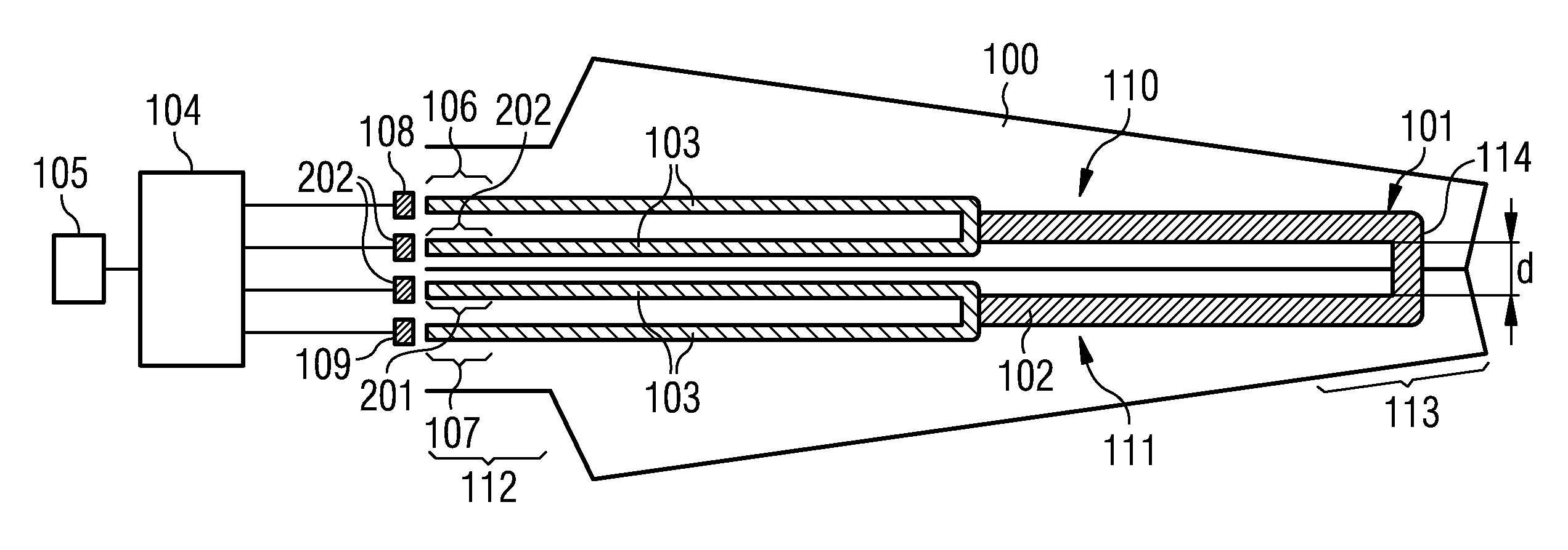
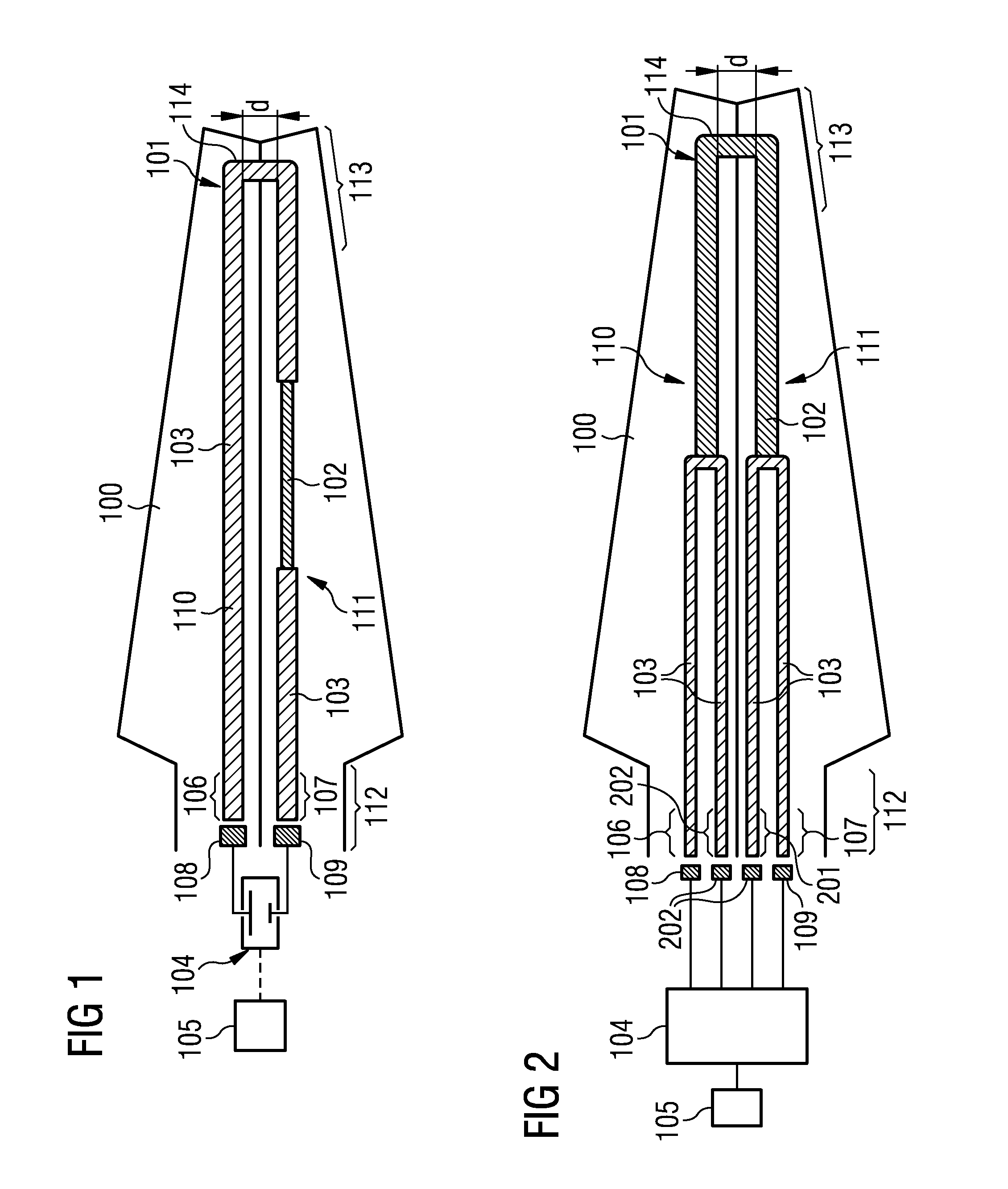
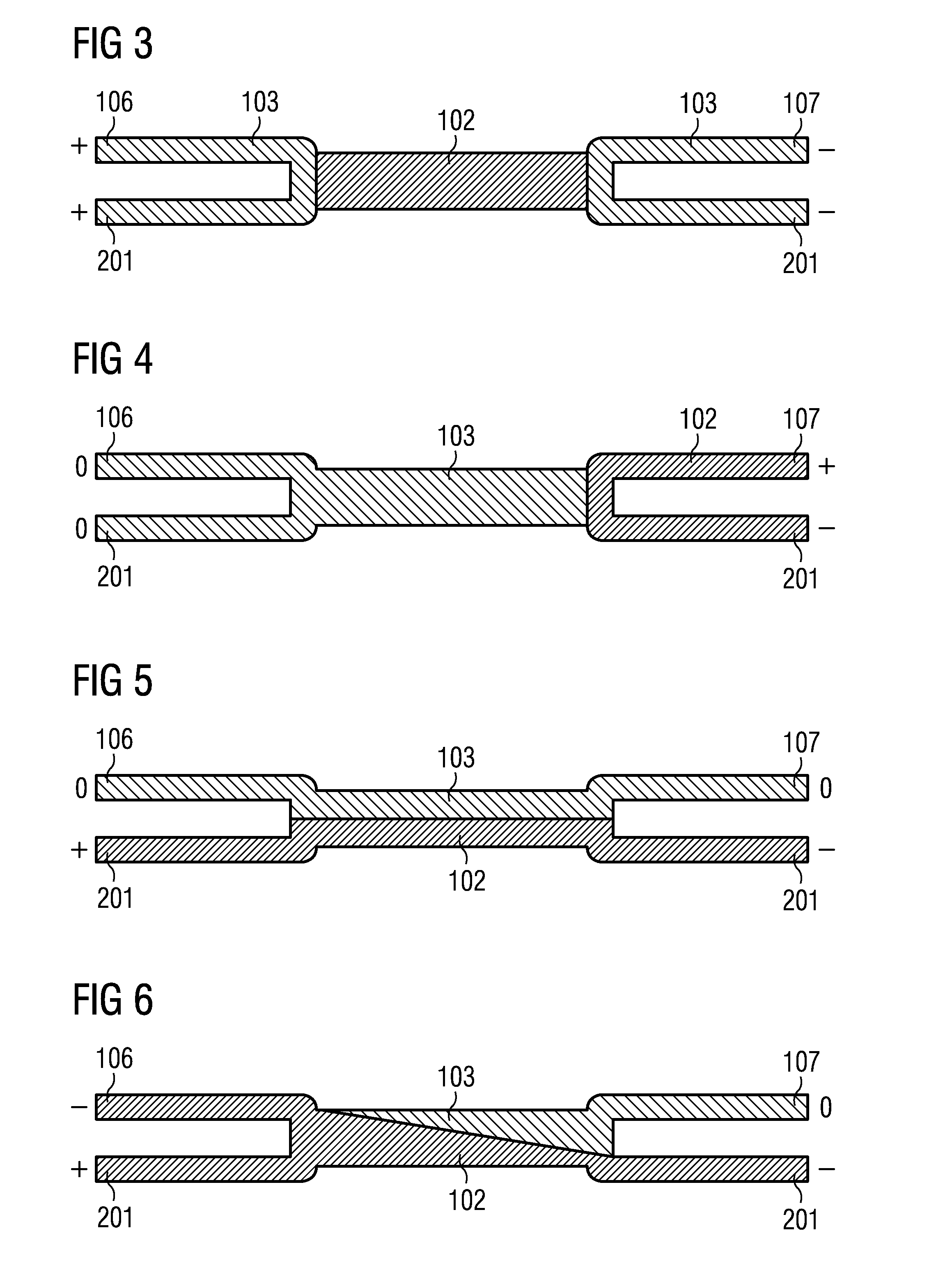
[0050]FIG. 1 shows a blade 100 for a wind turbine. The blade 100 comprises a heating mat 101 for generating heat by resistive heating. The heating mat 101 is mounted to the blade 100, in particular at an outer surface of the blade 100, wherein the heating mat 101 comprises a first heating power emitting section 102 for emitting a first heating power and a second heating power emitting section 103 for emitting a second heating power. The heating mat 101 is coupleable to a power supply unit 104 for transferring power to the heating mat 101 in such a way that the first heating power differs to the second heating power.

[0051]In the exemplary embodiment shown in FIG. 1, the first heating power emitting section 102 emits a higher first heating power in comparison to the second heating power emitting section 103 emitting th...


PUM


Abstract

The present invention describes a blade for a wind turbine. The blade includes a heating mat for generating heat by resistive heating, wherein the heating mat is mounted to the blade. The heating mat includes a first heating power emitting section for emitting a first heating power and a second heating power emitting section for emitting a second heating power. The heating mat is coupleable to a power supply unit for transferring power to the heating mat in such a way that the first heating power differs to the second heating power.

Description

FIELD OF INVENTION[0001]The present invention relates to a blade for a wind turbine and a method of producing a blade of a wind turbine.ART BACKGROUND[0002]Icing on any exposed part of a wind turbine can occur and cause decreased performance of the wind turbine. Furthermore e.g. when ice is accumulated on one or more of the rotor blades of a wind turbine, excess vibration problems from uneven blade icing may occur. This in turn may generate excessive mechanical loads on the wind turbine components leading eventually to wind turbine shut-down or to wind turbine faults.[0003]Hence, it is necessary to avoid ice or to remove ice located on wind turbine blades by a deicing system or by a heating system. In particular, it is known to use an electrical heating that is attached to an outer surfaces of the blade.[0004]In particular, there is also a need to heat the tip ends of the blades, so that in conventional heating systems a conductor has to run from the tip end to the root end of the b...

Claims


Application Information

Patent Timeline
IPC IPC(8): F03D11/00H05B3/02
CPCF03D11/0025Y02E10/722F05B2230/31F03D80/40Y02E10/72Y02P70/50
Inventor LAURBERG, HANS
Owner SIEMENS AG
Learn More