Fan assembly

a technology of fan assembly and fan body, which is applied in the direction of air heaters, free-cooling systems, machines/engines, etc., can solve the problems of affecting the appearance of the fan, affecting the operation of the fan, and the relative humidity detected by the sensor will not, at least initially, be indicative of the relative, etc., to achieve compact appearance, reduce the number of components, and reduce the effect of component number

Active Publication Date: 2013-01-31
DYSON TECH LTD
View PDF0 Cites 63 Cited by
  • Summary
  • Abstract
  • Description
  • Claims
  • Application Information

AI Technical Summary

Benefits of technology

[0019]In a preferred embodiment, the fan assembly comprises a humidifying system which is configured to increase the humidity of the second air flow before it is emitted from the nozzle. To provide the fan assembly with a compact appearance and with a reduced component number, at least part of the humidifying system may be located beneath the nozzle. At least part of the humidifying system may also be located beneath the impeller and the motor. For example, a transducer for atomizing water may be located beneath the nozzle. This transducer may be controlled by a controller that controls the motor. The second air passageway may be arranged to convey the second air flow over a reservoir for receiving water from the water tank and the transducer for atomizing water located in the reservoir.
[0020]The body may comprise a removable water tank for supplying water to the humidifying system. To provide the body with a compact appearance, the water tank preferably extends about the flow generating means. In a preferred embodiment, the water tank surrounds the flow generating means. The water tank may surround at least part of the first air passageway, and at least part of the second air passageway. The body may comprise a base comprising the air inlet through which air enters the fan assembly, and the water tank may be mounted on the base. Preferably, the base and the water tank each have a curved, for example cylindrical, outer surface, and the outer surfaces of the base and the water tank may have substantially the same radius. This can further contribute towards the compact appearance of the fan assembly.

Problems solved by technology

The water droplets enter the flow of air passing through the air duct, resulting in the emission of a mist into the environment.
Furthermore, as the relative humidity of the air in the local environment of the humidifier will rise relatively rapidly in comparison to that of the air in the local environment of the user, the relative humidity detected by the sensor will not, at least initially, be indicative of the relative humidity of the air local to the user.
Consequently, it may take a long period of time for the relative humidity of the air in the local environment of the user to reach the desired level.

Method used


Image

  • Fan assembly
  • Fan assembly
  • Fan assembly

Examples


Embodiment Construction

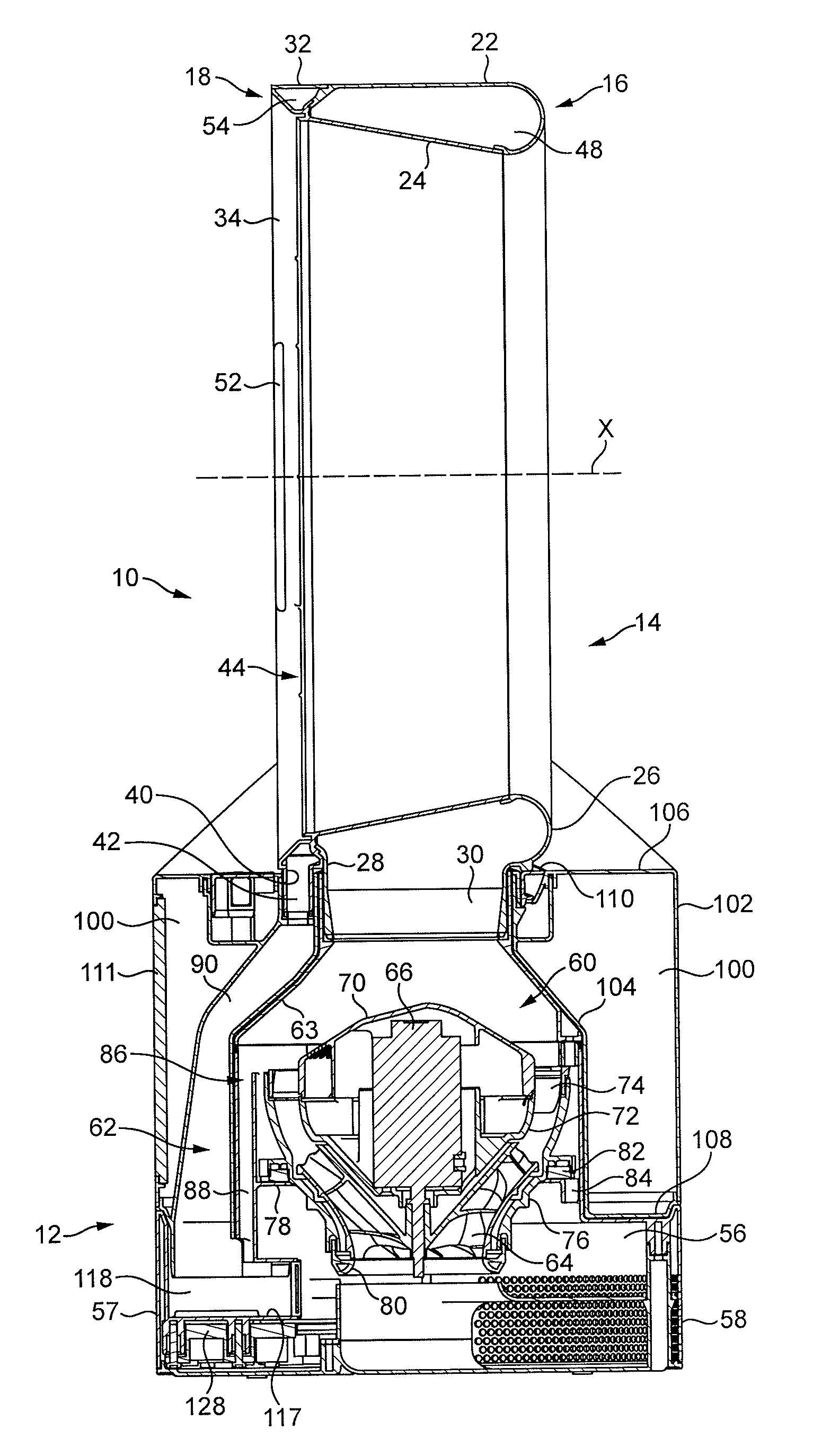
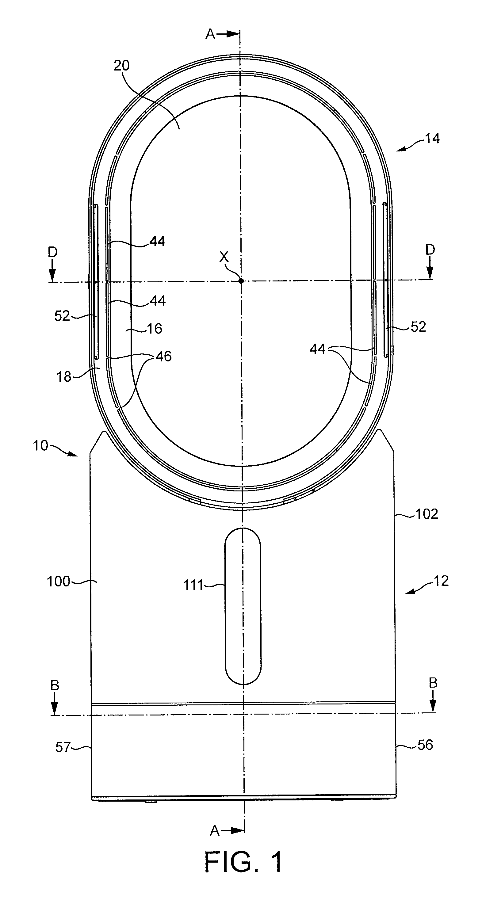
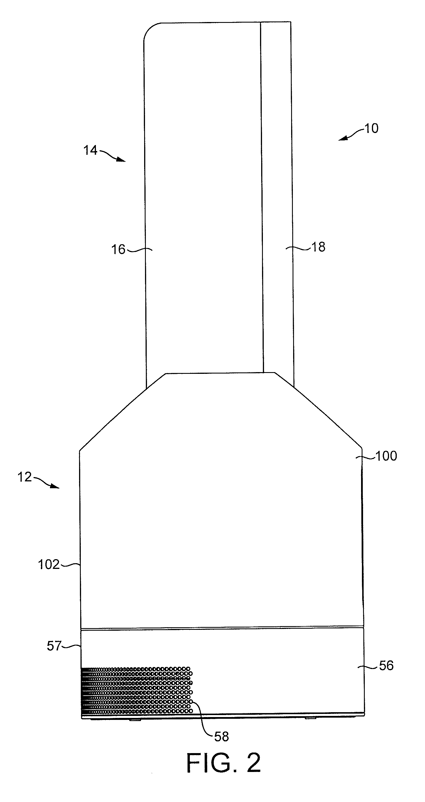
[0037]FIGS. 1 to 3 are external views of a fan assembly 10. In overview, the fan assembly 10 comprises a body 12 comprising an air inlet through which air enters the fan assembly 10, and a nozzle 14 in the form of an annular casing mounted on the body 12, and which comprises a plurality of air outlets for emitting air from the fan assembly 10.

[0038]The nozzle 14 is arranged to emit two different air flows. The nozzle 14 comprises a rear section 16 and a front section 18 connected to the rear section 16. Each section 16, 18 is annular in shape, and extends about a bore 20 of the nozzle 14. The bore 20 extends centrally through the nozzle 14 so that the center of each section 16, 18 is located on the axis X of the bore 20.

[0039]In this example, each section 16, 18 has a “racetrack” shape, in that each section 16, 18 comprises two, generally straight sections located on opposite sides of the bore 20, a curved upper section joining the upper ends of the straight sections and a curved lo...


PUM

PropertyMeasurementUnit
flow rateaaaaaaaaaa
widthaaaaaaaaaa
widthaaaaaaaaaa

Abstract

A fan assembly includes a nozzle and a body on which the nozzle is mounted. The nozzle has a first air inlet, a first air outlet, and a first interior passage for conveying air from the first air inlet to the first air outlet. The nozzle also includes a second air inlet, a plurality of second air outlets, and a second interior passage for conveying air from the second air inlet to the second air outlets. The body generates a first air flow through the first interior passage and a second air flow through the second interior passage. A first air passageway conveys the first air flow to the first air inlet and a second air passageway conveys the second air flow to the second air inlet. One of the temperature, humidity, composition and electrical charge of the second air flow is changed before it is emitted from the nozzle.

Description

REFERENCE TO RELATED APPLICATIONS[0001]This application claims the priority of United Kingdom Application No. 1112911.1, filed Jul. 27, 2011, United Kingdom Application No. 1203887.3, filed Mar. 6, 2012, and United Kingdom Application No. 1203888.1, filed Mar. 6, 2012, the entire contents of which are incorporated herein by reference.FIELD OF THE INVENTION[0002]The present invention relates to a fan assembly. In a preferred embodiment, the present invention provides a humidifying apparatus for generating a flow of moist air and a flow of air for dispersing the moist air within a domestic environment, such as a room, office or the like. The invention may also be used to disperse a hot, cool, scented or ionized air flow within an environment.BACKGROUND OF THE INVENTION[0003]Domestic humidifying apparatus is generally in the form of a portable appliance having a casing comprising a water tank for storing a volume of water, and a fan for creating a flow of air through an air duct of the...

Claims


Application Information

Patent Timeline
Patent Type & Authority Applications(United States)
IPC IPC(8): F24F5/00
CPCF04D25/08F04F5/16F24F1/01F24F6/14F04D29/705F24F2006/125F24F2221/28Y02B30/545Y02B30/80F24F13/26Y02B30/54Y02B30/70F04D29/441F04D29/545F24F6/12F24H3/0417B01J19/10F04F5/20F24F3/14F04D29/44F04D29/54F24F2006/008F24F2006/143
Inventor STANIFORTH, MARK JOSEPHPULLEN, JUDE PAUL
Owner DYSON TECH LTD
Why Eureka
Try Eureka