
Fiber Optic Sensor Thermally Matched Support Tubes for Distributed Fiber Optic Sensing

a fiber optic sensor and support tube technology, applied in the field of fiber optic sensors, can solve the problems of large differential expansion between optical fibers, too much insulation degradation, and limited ion release from these areas

Active Publication Date:
View PDF6 Cites 26 Cited by
  • Summary
  • Abstract
  • Description
  • Claims
  • Application Information

AI Technical Summary

Benefits of technology

The present invention provides a distributed fiber optic sensor that uses a composite support tube for at least one strand of optical fiber. The composite support tube is made of a pair of materials that have different thermal expansion coefficients, which helps to match the thermal expansion of the surrounding environment. This reduces the likelihood of temperature fluctuations causing damage or interference with the optical signal. The invention can be used on large electric generators and offers various other advantages such as improved sensitivity and durability.

Problems solved by technology

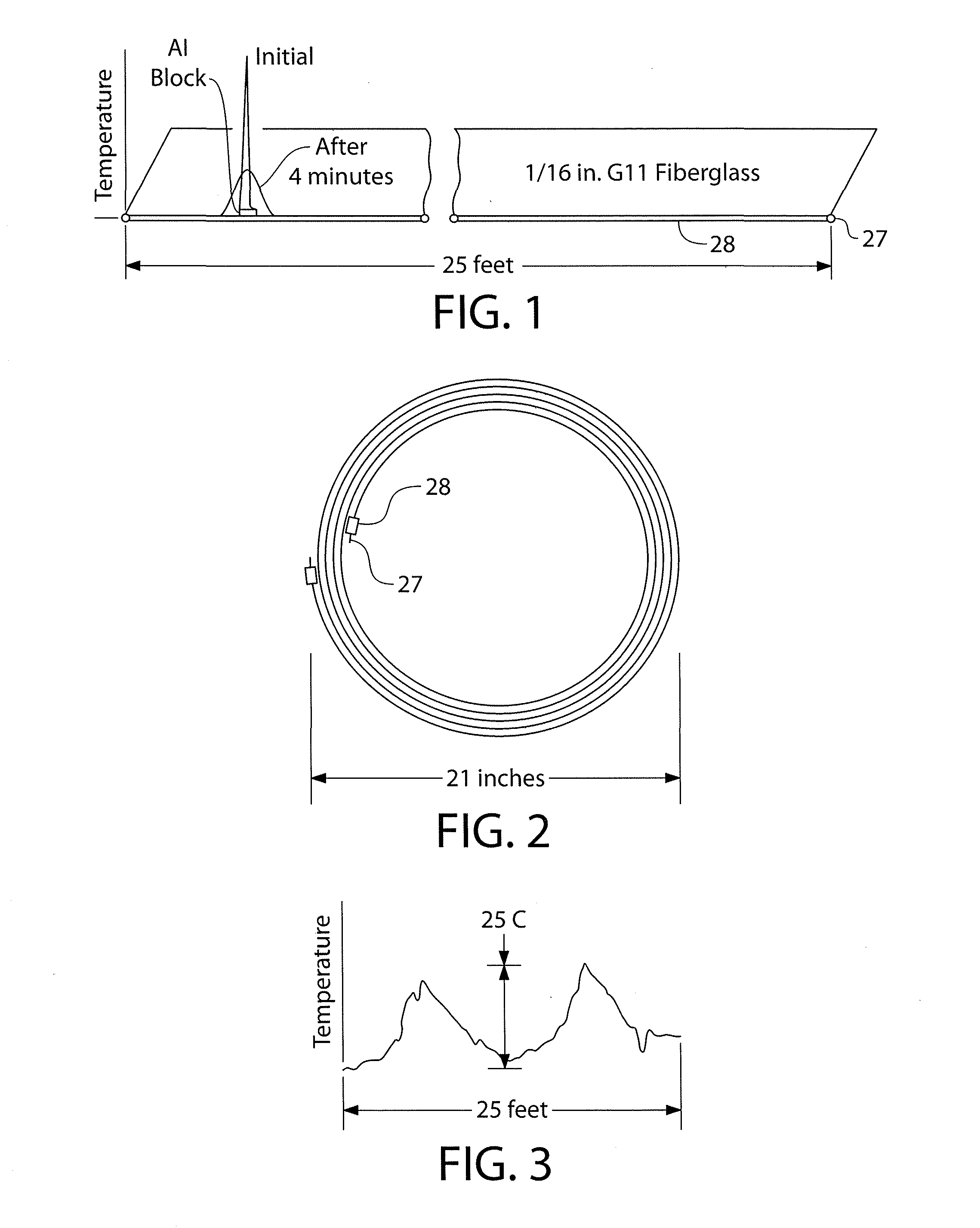
The entire long run would not suddenly experience a large temperature change which would cause a large differential expansion between the optical fiber and its support tube, which due to a stick slip phenomenon would then tend to concentrate the temperature measurement errors at certain points.
Unfortunately, the long time between stator core integrity tests has resulted in too much insulation degradation between inspections with the inevitable core failure, which then requires stripping the winding from the core, a full or partial restack of the stator laminations, followed with a complete rewind of the electrical machine.
This creates a sealed area around all the stator coils within the stator core making ion release from these areas very limited.
The core monitor needs to be quite sensitive to be effective and many times it will give a “false alarm.” In some situations, the core monitor will signal a problem, the operator will shut down the machine, open a cover and crawl inside and inspect what is visible.
If nothing is visibly overheated or obviously burned, they usually return the unit to service, risking an eventual stator core failure that was there but hidden from view.
Other times the machine continues running and the problem is found during the maintenance inspection described above.
If stator core alarms and subsequent crawl through inspections fail to isolate the cause, many operators will simply turn off the core monitor and take the risk of an eventual stator core failure.
This vibration has in many instances caused pieces of laminations and vent fingers to break off, becoming loose parts, and, as a direct consequence, cause a short to ground within the core.
This happens because cooling gas windage in conjunction with the magnetic forces can cause these loose pieces to vibrate and wear through the stator coil electrical stator coil ground-wall insulation, creating the short to ground and possibly significant core damage before the relays and breakers can trip the unit off line.
Stator coil movement is often referred to as slot pounding, which can quickly abrade the stator coil electrical ground-wall insulation leading to a short to ground once the stator coil ground-wall insulation gets too thin or cracks through due to the pounding.
Slot end stator coil vibration is undesirable but stator coil vibration within the great bulk of the stator core is also equally undesirable and is currently measured only by performing electrical generator partial disassembly and using the robotic wedge tap device approximately every five years.
With well over one-thousand (1000) top ripple springs in a single generator and six (6) optical fiber Bragg gratings required per top ripple spring, the complete ripple-spring-by-ripple spring stator coil tightness evaluation by means of individual fiber Bragg gratings would be associated with greater than desirable costs.
This disadvantage along with the difficulty of trying to link fibers between adjacent top ripple springs as these ripple springs are assembled by wedging and hammering them to a nearly flat condition would require a separate fiber for each top ripple spring, which is too many optical Fiber Bragg Grating-type sensing fibers to consider as a solution.
The top ripple springs are also highly stressed thin (0.8 mm) components subject to cracking which makes cutting grooves into the ripple springs and bonding in fiber Bragg gratings a questionable practice.
It has been found that due to the geometry of large electric generators, requiring many bends and / or loops and not just straight sections, greater than desirable errors have been measured by using conventional fiber optic sensors.

Method used


Image

  • Fiber Optic Sensor Thermally Matched Support Tubes for Distributed Fiber Optic Sensing
  • Fiber Optic Sensor Thermally Matched Support Tubes for Distributed Fiber Optic Sensing
  • Fiber Optic Sensor Thermally Matched Support Tubes for Distributed Fiber Optic Sensing

Examples


Embodiment Construction

[0056]Prior to proceeding to the more detailed description of the present invention, it should be noted that, for the sake of clarity and understanding, identical components which have identical functions have been identified with identical reference numerals throughout the several views illustrated in the drawing figures.

[0057]The present invention is illustrated and described in combination with a large AC electric generator, although it will be apparent to those skilled in the relevant art that the present invention may be applied to other devices or structures and as such should not be interpreted as a limiting factor of the distributed fiber optic sensor of the instant invention.

[0058]FIG. 12 shows a typical AC electric generator including the frame 1 within which is contained the stator core 2 integral electrically conductive windings showing the end regions 3 and rotor 4 Also shown are the parallel rings 5 which are connected to the main leads (typically six(6)) 6.

[0059]FIG. ...


PUM

PropertyMeasurementUnit
frequenciesaaaaaaaaaa
voltageaaaaaaaaaa
lengthaaaaaaaaaa

Abstract

Distributed fiber optic sensor includes a composite support tube that closely matches the coefficient of thermal expansion of the optical sensing fiber contained therewithin for applications including but not limited to Rayleigh back-scattering, (OFDR, Optical Frequency Domain Reflectometry), Brillouin frequency shift (BOTDA, Brillouin Optical Time Domain Analysis, BOTDR, Brillouin Optical Time Domain Reflectometry), Raman (Optical Time Domain Reflectometry), DPP-BOTDA (Differential Pulse Pair Brillouin Optical Time Domain Analysis), Dual-Index BOTDA, PCF (Photonic Crystalline Fibers), and dense packed Fiber Bragg Gratings, both time and wave length modulated are described in detail.

Description

CROSS-REFERENCE TO RELATED APPLICATIONS[0001]This application is related to and claims priority from U.S. Provisional Patent Application Ser. No. 61 / 572,867 filed on Jul. 25, 2011. This application is also closely related to U.S. regular Utility patent application Ser. No. 13 / 065,842 filed on Mar. 31, 2011 by inventor of the instant invention and titled “Use of fiber optic sensor techniques for monitoring and diagnostics of large AC generators”. Teaching of the U.S. regular Utility patent application Ser. No. 13 / 065,842 is incorporated in this document by reference thereto.FIELD OF THE INVENTION[0002]The present invention relates, in general, to fiber optic sensors and, more particularly, this invention relates to a fiber optic sensors having thermally matched support member encasing at least one strand of optical fiber, yet more particularly, the instant invention relates to fiber optic sensors employing thermally matched support member for use in electric generators.STATEMENT REGA...

Claims


Application Information

Patent Timeline
Patent Type & Authority Applications(United States)
IPC IPC(8): G02B6/00B32B1/00B32B1/08B32B7/02
CPCB32B7/02B32B1/00B32B1/08G02B6/00Y10T428/24942G01K11/3206G01D5/35358Y10T428/13G01K11/32G01D5/35316
Inventor DAILEY, GEORGE FRANKLIN
Learn More