Coated article and method for making the same

a technology of coated articles and coatings, applied in the direction of superimposed coating process, ceramic layered products, transportation and packaging, etc., can solve the problems of accelerating the galvanic corrosion of the substrate, and reducing the standard electrode potential of aluminum alloy or magnesium alloy

Inactive Publication Date: 2013-01-31
HONG FU JIN PRECISION IND (SHENZHEN) CO LTD +1
View PDF6 Cites 11 Cited by
  • Summary
  • Abstract
  • Description
  • Claims
  • Application Information

AI Technical Summary

Problems solved by technology

The standard electrode potential of aluminum alloy or magnesium alloy is very low.
When the aluminum alloy or magnesium alloy substrate is coated with a layer using physical vapor deposition (PVD) technology, the substrate often suffers galvanic corrosion due to the high potential difference between the layer and the substrate.
Furthermore, the layer made by PVD will have tiny openings such as pinholes and cracks, which can accelerate the galvanic corrosion of the substrate.

Method used


Image

  • Coated article and method for making the same
  • Coated article and method for making the same
  • Coated article and method for making the same

Examples


example 1

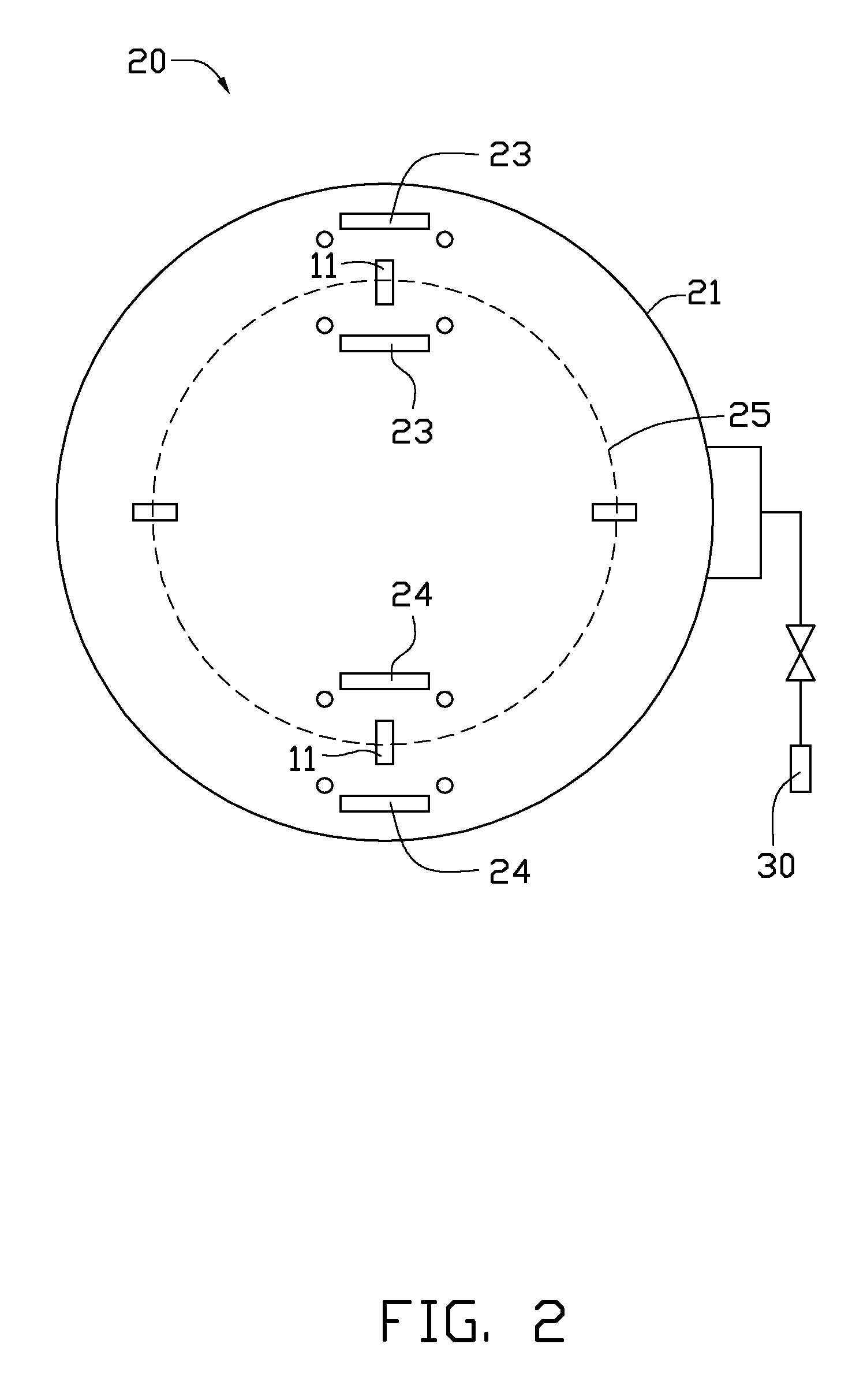
[0018]The vacuum sputtering device 20 in example 1 was a medium frequency magnetron sputtering device.

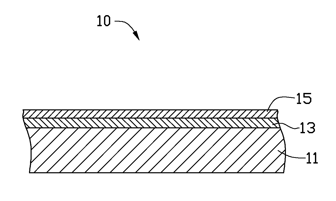
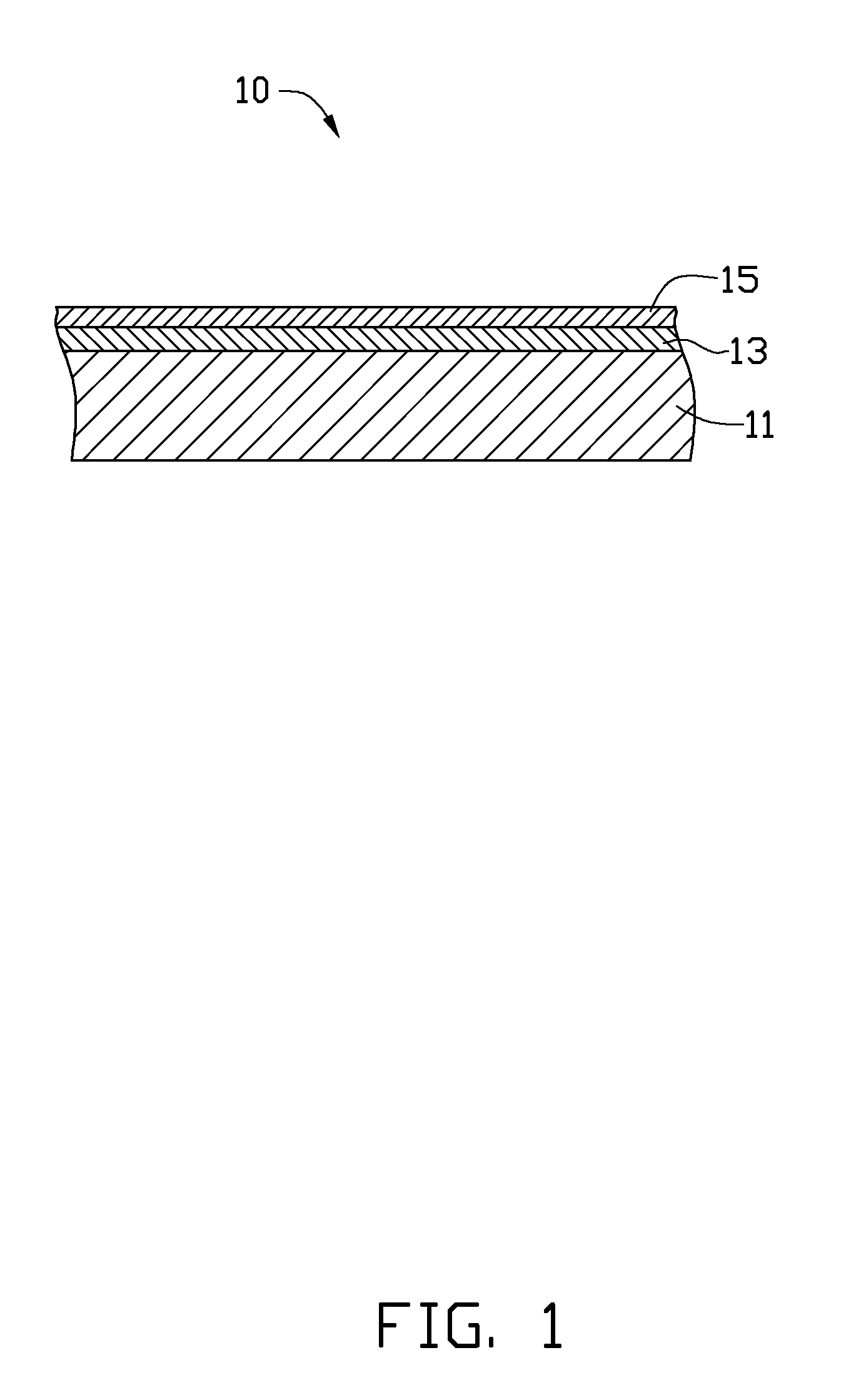
[0019]The substrate 11 was made of magnesium alloy.

[0020]Sputtering to form the anti-corrosion layer 13 on the substrate 11 took place, wherein the vacuum chamber 21 was heated to a temperature of about 100° C. Ar was fed into the vacuum chamber 21 at a flow rate of about 180 sccm. The first targets 23 were supplied with a power of about 8 kw, and a negative bias voltage of about −75 V was applied to the substrate 11. Deposition of the anti-corrosion layer 13 took a total of about 45 min. The anti-corrosion layer 13 had a thickness of about 800 nm.

[0021]Sputtering to form the decorative layers 15 on the anti-corrosion layer 13 took place, wherein the second targets 24 were supplied with a power of about 8 kw. N2 was fed into the vacuum chamber 21 at a flow rate of about 100 sccm. Other conditions were substantially the same as vacuum sputtering of the anti-corrosion layer 13. The de...

example 2

[0022]The vacuum sputtering device 20 in example 2 was the same in example 1.

[0023]The substrate 11 was made of aluminum alloy.

[0024]Sputtering to form the anti-corrosion layer 13 on the substrate 11 took place, wherein the vacuum chamber 21 was heated to a temperature of about 100° C. Ar was fed into the vacuum chamber 21 at a flow rate of about 250 sccm. The first targets 23 were supplied with a power of about 10 kw, and a negative bias voltage of about −100 V was applied to the substrate 11. Deposition of the anti-corrosion layer 13 took a total of about 45 min. The anti-corrosion layer 13 had a thickness of about 1200 nm.

[0025]Sputtering to form the decorative layers 15 on the anti-corrosion layer 13 took place, wherein the second targets 24 were supplied with a power of about 8 kw. N2 was fed into the vacuum chamber 21 at a flow rate of about 120 sccm. Other conditions were substantially the same as vacuum sputtering of the anti-corrosion layer 13. The deposition of the decorat...


PUM

PropertyMeasurementUnit
thicknessaaaaaaaaaa
thicknessaaaaaaaaaa
temperatureaaaaaaaaaa

Abstract

A coated article includes a substrate, an anti-corrosion layer formed on the substrate, and a decorative layer formed on the anti-corrosion layer. The anti-corrosion layer is an amorphous alloy layer containing elements of iron, chromium, boron and M, wherein M is one or more selected from the group consisting of phosphorus, carbon and silicon. A method for making the coated article is also described.

Description

BACKGROUND[0001]1. Technical Field[0002]The present disclosure relates to coated articles and a method for making the coated articles.[0003]2. Description of Related Art[0004]The standard electrode potential of aluminum alloy or magnesium alloy is very low. When the aluminum alloy or magnesium alloy substrate is coated with a layer using physical vapor deposition (PVD) technology, the substrate often suffers galvanic corrosion due to the high potential difference between the layer and the substrate. Furthermore, the layer made by PVD will have tiny openings such as pinholes and cracks, which can accelerate the galvanic corrosion of the substrate.[0005]Therefore, there is room for improvement within the art.BRIEF DESCRIPTION OF THE FIGURE[0006]Many aspects of the coated article and the method for making the coated article can be better understood with reference to the following drawings. The components in the drawings are not necessarily drawn to scale, the emphasis instead being pla...

Claims


Application Information

Patent Timeline
Patent Type & Authority Applications(United States)
IPC IPC(8): B32B15/04B32B18/00C23C14/35B32B15/01
CPCC23C14/0641C23C28/323Y10T428/12757C23C28/34Y10T428/12576C23C14/0036Y10T428/265Y10T428/12729Y10T428/12611C23C14/024
Inventor CHIANG, HUANN-WUCHEN, CHENG-SHILI, CONG
Owner HONG FU JIN PRECISION IND (SHENZHEN) CO LTD
Why Eureka
Try Eureka