Current sensor

a current sensor and sensor technology, applied in the field of current sensors, can solve the problems of increasing the size of the current sensor itself, increasing the complexity of the configuration, increasing the design and construction difficulty, etc., and achieves the effects of reducing the size of the current sensor, simple configuration, and small measurement curren

Inactive Publication Date: 2013-02-07
ALPS GREEN DEVICES
View PDF0 Cites 17 Cited by
  • Summary
  • Abstract
  • Description
  • Claims
  • Application Information

AI Technical Summary

Benefits of technology

[0010]The present invention has been made in view of the above-described problem, and provides a current sensor which achieves reducti

Problems solved by technology

However, a larger magnetic core unfortunately results in an increase in the size of the current sensor itself.
A configuration using a magnetoresistive element instead of a magnetic core is subjected to an influence of the external magnetic field, and therefore needs a magnetic shield to reduce the influence, resulting in an increase in difficulty in the design and an increase in complexity of the configuration.
This leads to a problem of an increase in cost o

Method used


Image

  • Current sensor
  • Current sensor
  • Current sensor

Examples


Embodiment Construction

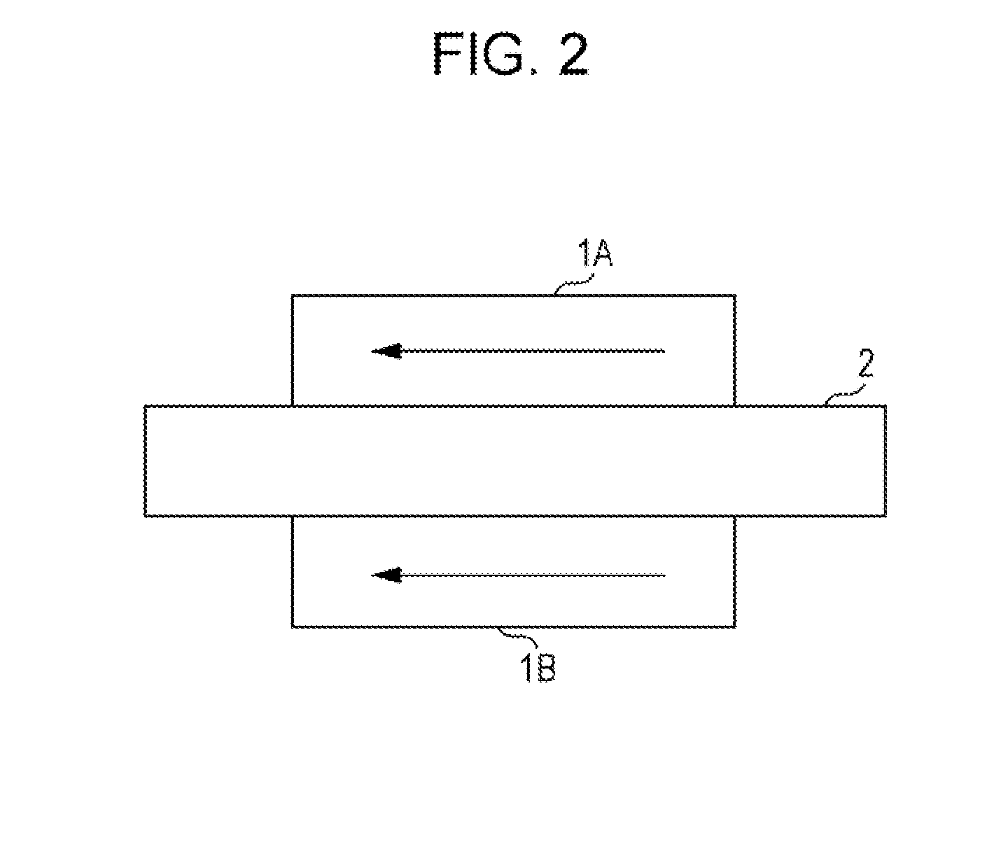
[0026]An Embodiment of the present invention will be described in detail below with reference to the accompanying drawings. Herein, a current sensor will be described which includes two magnetic balance sensors, one of which continuously operates, and the other of which is turned on / off. In the present invention, a current sensor may include three magnetic balance sensors or more.

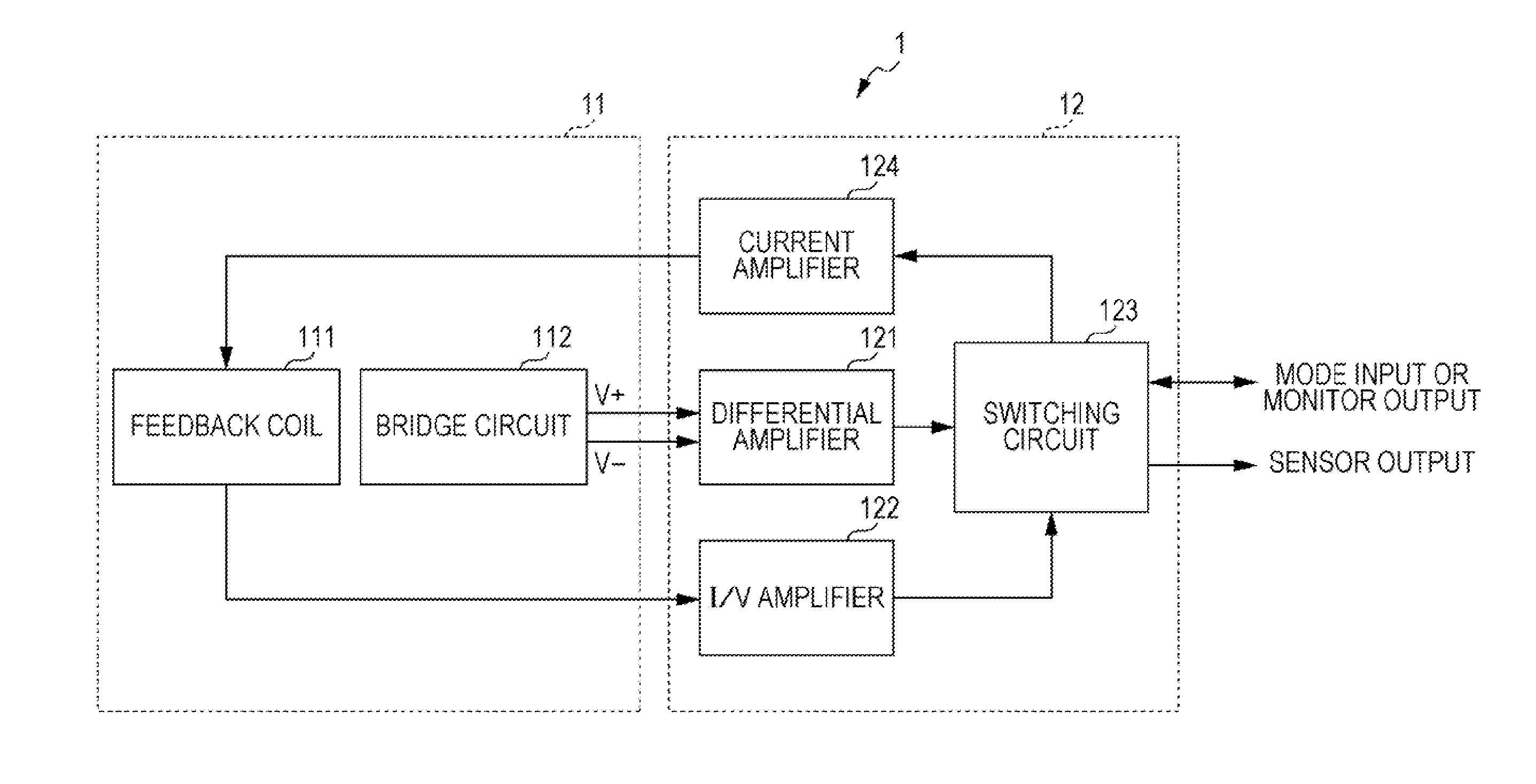
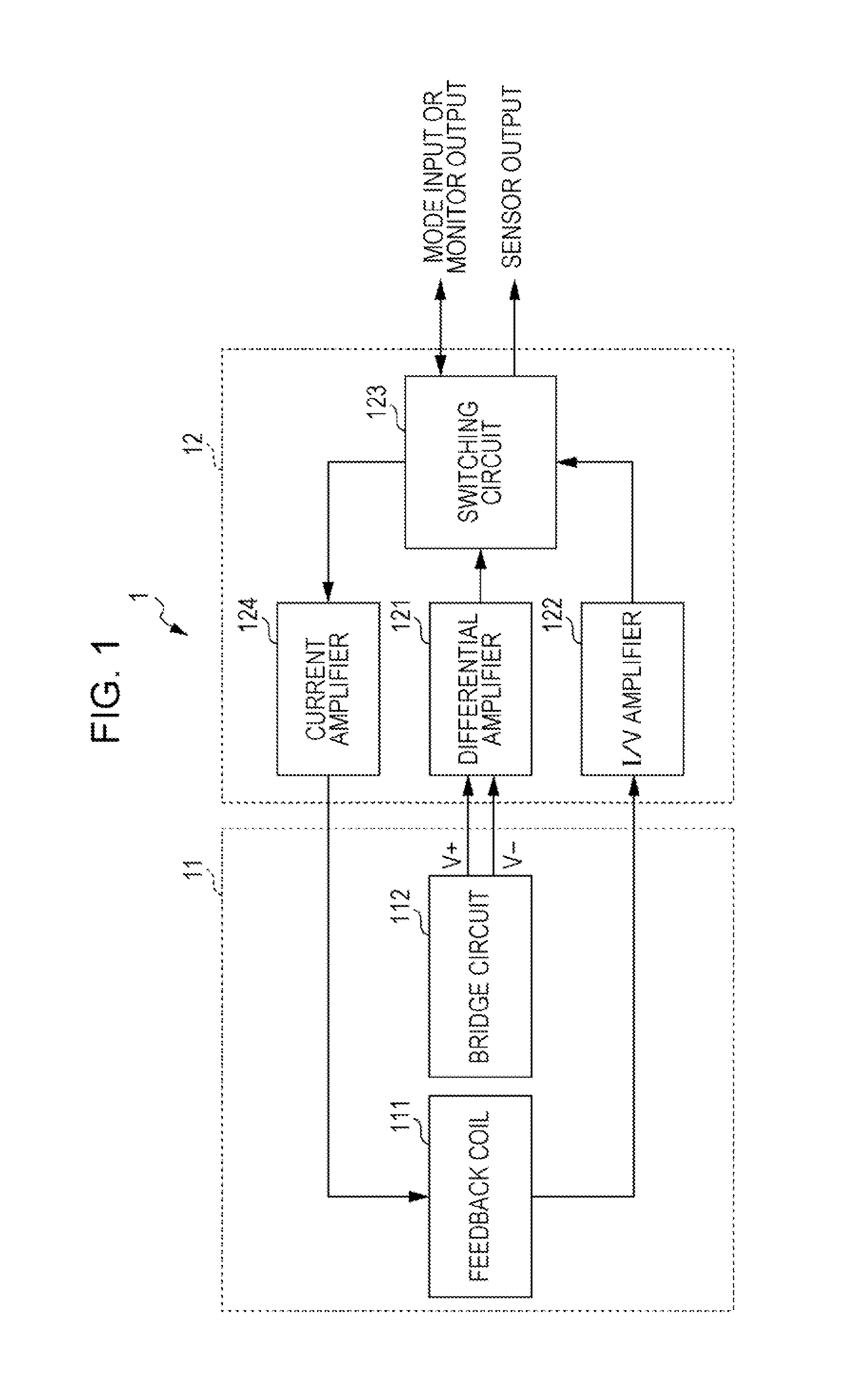
[0027]FIG. 1 is a diagram illustrating a current sensor including one magnetic balance sensor, according to the embodiment of the present invention. In the embodiment, a current sensor 1 illustrated in FIG. 1 is disposed near a current line through which a measurement current flows. The current sensor 1 mainly includes a sensing unit 11 and a controller 12.

[0028]The sensing unit 11 includes a feedback coil 111 which is disposed in such a manner that a magnetic field can be produced in a direction in which a magnetic field caused by the measurement current is canceled, and a bridge circuit 112 which includes...


PUM


Abstract

A current sensor includes a pair of magnetic balance sensors and a switching circuit. The magnetic balance sensors each include a magnetic sensor element and a feedback coil. The magnetic sensor element varies in characteristics due to an induction field caused by measurement current. The feedback coil is disposed near the magnetic sensor element and produces a canceling magnetic field canceling out the induction field. Each of the magnetic balance sensors outputs, as a sensor output, a value corresponding to current flowing through the feedback coil when a balanced state in which the induction field and the canceling magnetic field cancel each other out is reached after the feedback coil is energized. The switching circuit turns on/off one of the magnetic balance sensors.

Description

CLAIM OF PRIORITY[0001]This application is a Continuation of International Application No. PCT / JP2011 / 059445 filed on Apr. 15, 2011, which claims benefit of Japanese Patent Application No. 2010-100948 filed on Apr. 26, 2010. The entire contents of each application noted above are hereby incorporated by reference.BACKGROUND OF THE INVENTION[0002]1. Field of the Invention[0003]The present invention relates to a current sensor employing a magnetoresistive element.[0004]2. Description of the Related Art[0005]In electric cars, a motor is driven using power generated by an engine. The magnitude of current for driving the motor is detected, for example, using a current sensor. One example of such current sensors is a sensor which includes a magnetic core that has a cutout portion (core gap) in a portion thereof and that is disposed around a conductor, and a magnetic sensor element disposed in the core gap (see Japanese Unexamined Patent Application Publication No. 2007-212306). In this cur...

Claims


Application Information

Patent Timeline
IPC IPC(8): G01R33/038G01R33/09
CPCG01R15/207G01R15/205G01R31/3696G01R33/0041G01R31/364
Inventor NOMURA, MASATOSHI
Owner ALPS GREEN DEVICES
Why Eureka
Try Eureka