Antenna device

a technology of an antenna and a divider, which is applied in the direction of linear waveguide fed arrays, antennas, leaky waveguide antennas, etc., can solve the problems of difficult partition disposal and the inability to obtain the offset effect from the outermost waveguid

Active Publication Date: 2013-02-07
HONDA ELESYS CO LTD
View PDF4 Cites 51 Cited by
  • Summary
  • Abstract
  • Description
  • Claims
  • Application Information

AI Technical Summary

Benefits of technology

[0034]As described above, according to the various aspects of the present invention, it is possible to provide a high-efficiency antenna device used in the on-vehicle radar device.

Problems solved by technology

Here, it is difficult to dispose a partition for separating waveguides and the slot plate without having any gap therebetween; however, a method of suppressing the leakage of radio wave between waveguides by supplying power to the neighboring linear array in a reverse phase is known.
However, the offsetting effect cannot be obtained from the outermost waveguide, and other measures are necessary.

Method used


Image

  • Antenna device
  • Antenna device
  • Antenna device

Examples


Embodiment Construction

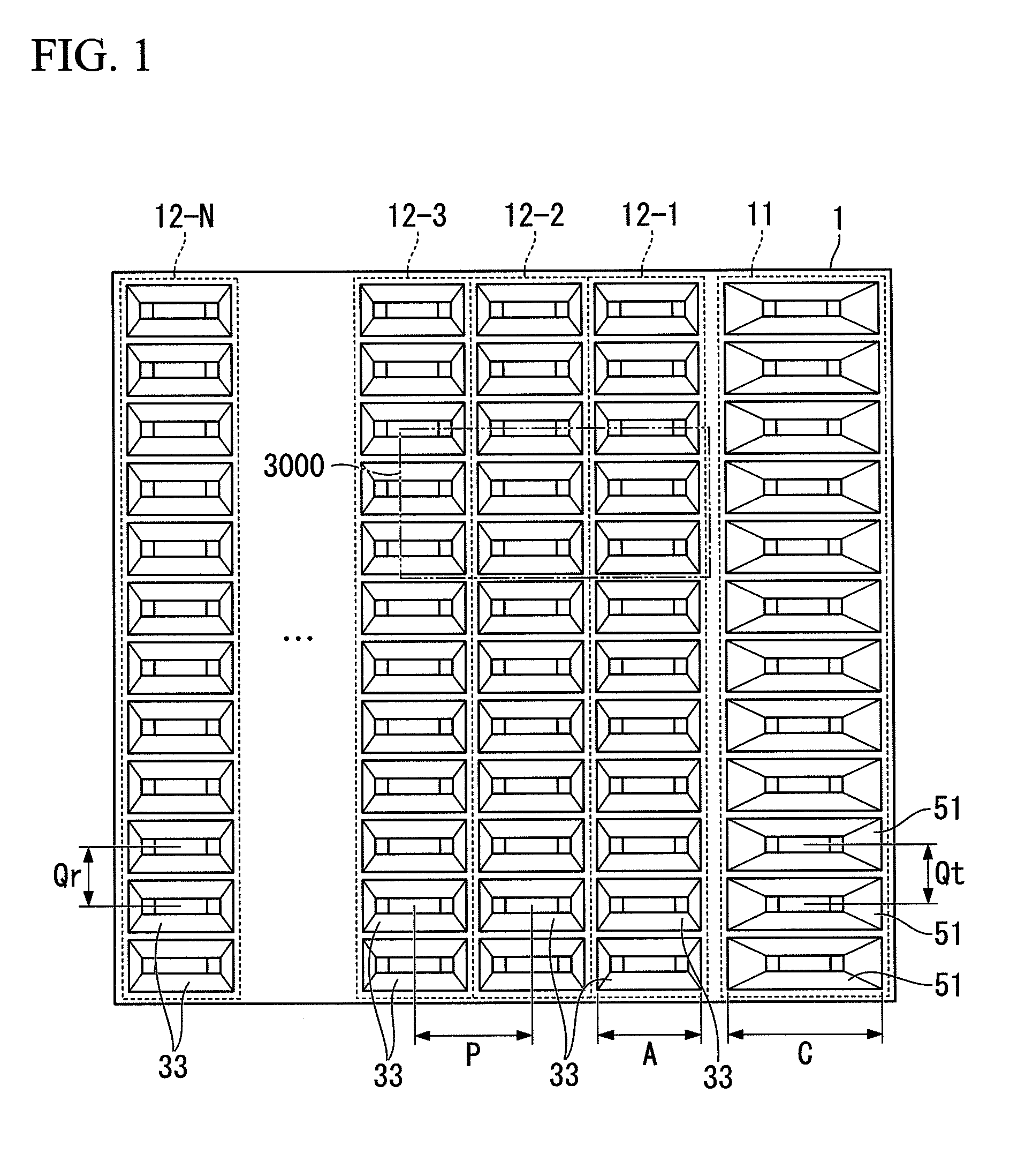
[0050]FIG. 1 is a front view showing the structure of an antenna device (a radar antenna 1) installed in an on-vehicle radar device according to an embodiment of the present invention.

[0051]In the present embodiment, the arrangement and configuration of the antenna device (the radar antenna 1) installed in the radar device performing DBF is shown.

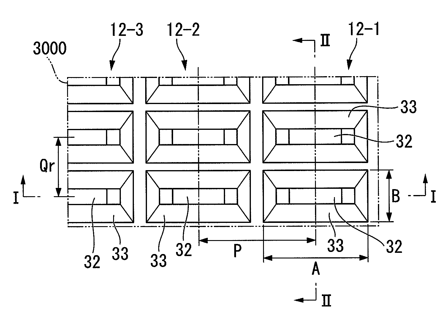
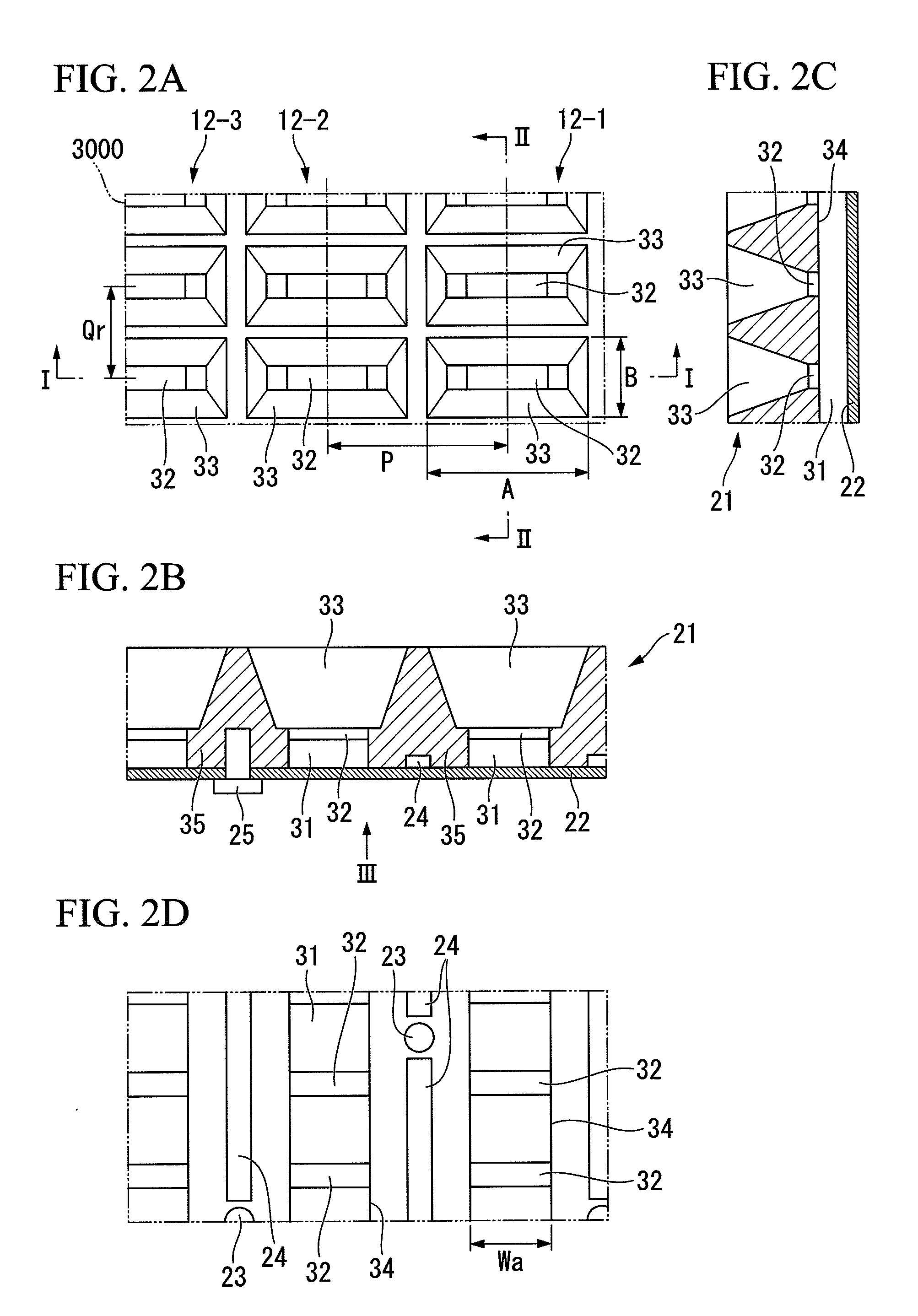
[0052]FIGS. 2A to 2D are views showing the structure (the stereoscopic structure) of the antenna device installed in the on-vehicle radar device according to the embodiment of the present invention. FIG. 2A is a front view of the scope 3000 of a section surrounded by a two-dot chain line shown in FIG. 1, FIG. 2B is a transverse cross-sectional view taken along the cutting line I-I in the transverse direction in FIG. 2A, FIG. 2C is a longitudinal cross-sectional view taken along cutting line II-II is the longitudinal direction perpendicular to the transverse direction in FIG. 2A, and FIG. 2D is a rear view of the metal plate 22 seen in the h...


PUM


Abstract

An antenna device includes antennas, each of which includes antenna elements arranged in a longitudinal direction, arranged side by side in a transverse direction intersecting the longitudinal direction, wherein an interval between the antennas arranged side by side in the transverse direction is approximately 2λ. where λ is a free space wavelength corresponding to an operating frequency, and each of the antenna elements includes a horn formed therein.

Description

CROSS-REFERENCE TO RELATED APPLICATIONS[0001]Priority is claimed on Japanese Patent Application No. 2011-169303, filed Aug. 2, 2011, the contents of which are entirely incorporated herein by reference.BACKGROUND OF THE INVENTION[0002]1. Field of the Invention[0003]The present invention relates to an antenna device which can be used in an on-vehicle radar device for monitoring the driving direction of cars.[0004]2. Background Art[0005]An on-vehicle radar device has a radar function using millimeter waves, for example, and improves the driving safety of a car, so the development of a device with higher performance and lower price is under way for its dissemination. Such an on-vehicle radar device performs digital beam forming (DBF), for example.[0006]The radar device performing DBF includes a plurality of columns of receiving antennas arrayed in the transverse direction and generates scanning beams by converting receiving signals from each receiving antenna into digital data, a giving...

Claims


Application Information

Patent Timeline
Patent Type & Authority Applications(United States)
IPC IPC(8): H01Q13/02
CPCH01Q13/02H01Q21/064H01Q21/005H01Q13/22
Inventor ABE, AKIRA
Owner HONDA ELESYS CO LTD
Why Eureka
Try Eureka