
Backlight module and liquid crystal display

a backlight module and liquid crystal display technology, applied in the field of backlight modules and liquid crystal displays, can solve the problems of compromising the aesthetic appearance and display effect, and it is difficult to precisely determine the gap between the light guide plate and the plastic frame and the back frame, so as to save both the product cost and the mold cost, and improve the light unitization factor of the leds and the quality of the lcd panel.

Active Publication Date: 2013-02-07
SHENZHEN CHINA STAR OPTOELECTRONICS TECH CO LTD
View PDF2 Cites 19 Cited by
  • Summary
  • Abstract
  • Description
  • Claims
  • Application Information

AI Technical Summary

Benefits of technology

The present disclosure provides a backlight module and LCD with an optimized structure that improves the utilization factor of LEDs. The elastic corner parts are placed at the diagonal corners of the backlight module to accommodate the light guide plate and provide cushioning performance and appropriate hardness for thermal expansion and contraction. The hardness of the elastic corner parts is set to ensure the light mixing distance between LEDs and the light guide plate, which improves the light utilization factor of the LEDs and quality of the LCD panel. Additionally, the use of elastic corner parts eliminates the need for a plastic frame, saving both product and mold costs.

Problems solved by technology

Because of thermal expansion and contraction of the light guide plate and because the light mixing distance of the LEDs must be considered, it is difficult to precisely determine a gap between the light guide plate and the plastic frame and the back frame.
Specifically, if the gap is too small, the light guide plate tends to warp due to an insufficient space for thermal expansion and contraction, and this would compromise the aesthetic appearance and the displaying effect of the LCD; and otherwise, if the gap is too large, then the light guide plate tends to sway in the backlight module, which might cause noises and is unfavorable for a narrow side-frame design of the LCD.

Method used


Image

  • Backlight module and liquid crystal display
  • Backlight module and liquid crystal display
  • Backlight module and liquid crystal display

Examples


Embodiment Construction

[0036]Hereinbelow, the present disclosure will be further described with reference to the attached drawings and embodiments thereof. It shall be understood that, the embodiments described herein are only intended to illustrate but not to limit the present disclosure.

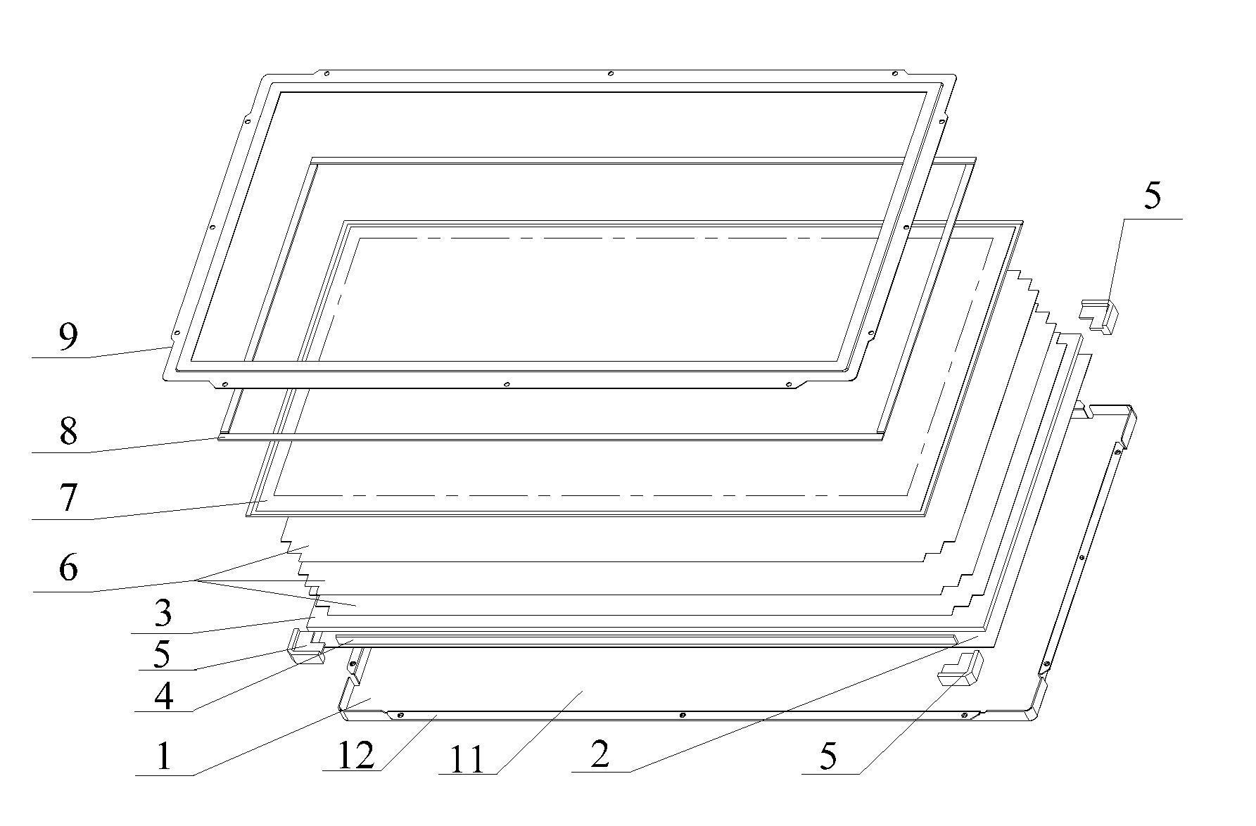
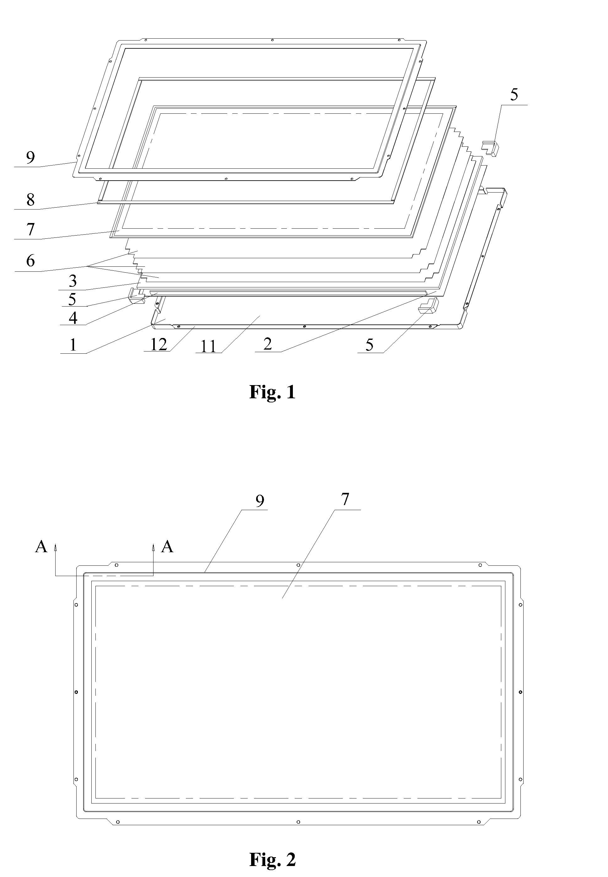
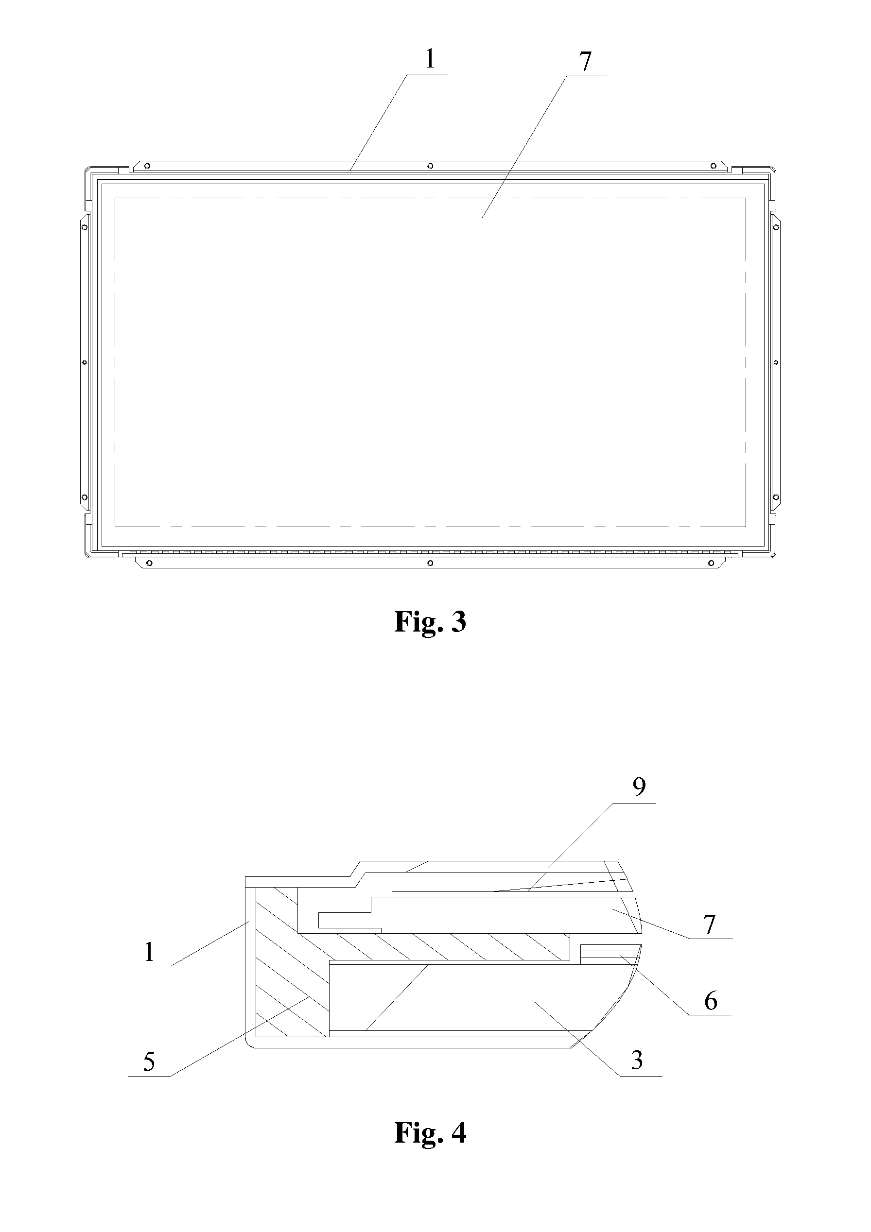
[0037]Referring to FIG. 1 to FIG. 4, FIG. 1 is a schematic exploded structural view of a first embodiment of a backlight module according to the present disclosure, FIG. 2 is a top view of the first embodiment of the backlight module according to the present disclosure, FIG. 3 is a top view of the first embodiment of the backlight module according to the present disclosure with a front frame thereof being removed, and FIG. 4 is a schematic enlarged cross-sectional view taken along a line A-A shown in FIG. 2. The backlight module according to the first embodiment of the present disclosure is an LED backlight module of the edge-lit type, which comprises a back frame 1, a light guide plate 3 disposed in the back frame 1, an...


PUM

PropertyMeasurementUnit
elasticaaaaaaaaaa
hardnessaaaaaaaaaa
thermal expansionaaaaaaaaaa

Abstract

A backlight module comprises a back frame, a light guide plate disposed in the back frame, and elastic corner parts for locating the light guide plate. The elastic corner parts are disposed at diagonal corners of the backlight module and sandwiched between the back frame and the light guide plate. The elastic corner parts can locate the light guide plate in the back frame, and the desirable cushioning performance and appropriate hardness of the elastic corner parts provide a desirable space for thermal expansion and contraction of the light guide plate. Meanwhile, the elastic corner part corresponding to the light incident side is greater than that of the non-light-incident sides for ensuring the light mixing distance between the LEDs and the light incident side of the light guide plate, which can improve the light unitization factor of the LEDs and save both the product cost and the mold cost.

Description

BACKGROUND[0001]1. Technical Field[0002]The present disclosure relates to the technical field of liquid crystal displays (LCDs), and more particularly, to a backlight module and an LCD.[0003]2. Description of Related Art[0004]As consumers' demands for energy-saving and environment-friendly products increase, LCDs adopting light emitting diodes (LEDs) as a backlight source have gradually become the mainstream product in the display market.[0005]Currently, LED light sources in backlight modules of the LCDs are primarily divided into two types: the edge-lit type and the direct-lit type. In an LED backlight module of the edge-lit type, a PMMA (polymethyl methacrylate) light guide plate (LGP) needs to be used. Because of thermal expansion and contraction of the light guide plate and because the light mixing distance of the LEDs must be considered, it is difficult to precisely determine a gap between the light guide plate and the plastic frame and the back frame. Specifically, if the gap ...

Claims


Application Information

Patent Timeline
Patent Type & Authority Applications(United States)
IPC IPC(8): G02F1/13357F21V8/00
CPCG02F1/133615G02F2201/54G02F2201/503
Inventor LI, QUANHSIAO, YU-CHUN
Owner SHENZHEN CHINA STAR OPTOELECTRONICS TECH CO LTD
Learn More