

Gas filling method, gas filling system, gas station and mobile unit
- Summary
- Abstract
- Description
- Claims
- Application Information
AI Technical Summary
Benefits of technology
Problems solved by technology
Method used
Image

Examples
Embodiment Construction
[0054]Hereinafter, an embodiment of the invention will be described with reference to the accompanying drawings.
1. Outline of Gas Filling System
[0055]Here, an example in which hydrogen gas is filled from a hydrogen station into a tank of a fuel cell vehicle equipped with a fuel cell system will be described as a gas filling system. The fuel cell system includes a fuel cell, or the like, that generates electricity by electrochemical reaction between fuel gas (for example, hydrogen gas) and oxidant gas (for example, air) as is known publicly. In addition, filling hydrogen gas is one of modes for supplying hydrogen as from the hydrogen station to the tank.
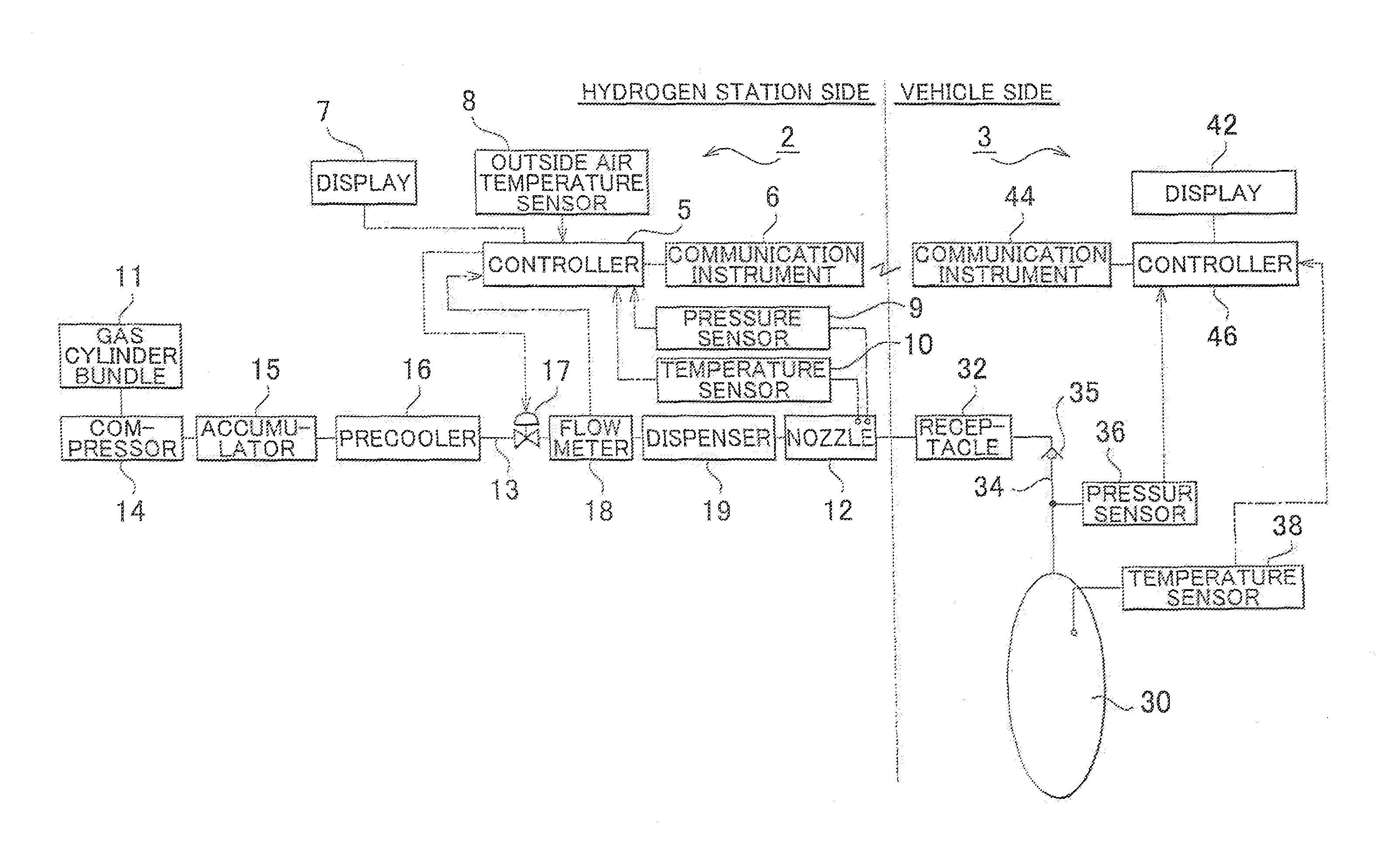
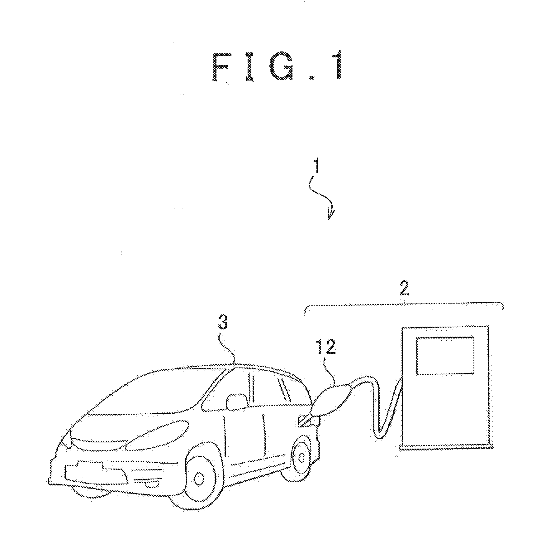
[0056]As shown in FIG. 1, the gas filling system 1, for example, includes a hydrogen station 2 that serves as a gas station, and a vehicle 3 that is supplied With hydrogen gas from the hydrogen station 2.
1-1. Outline of Vehicle
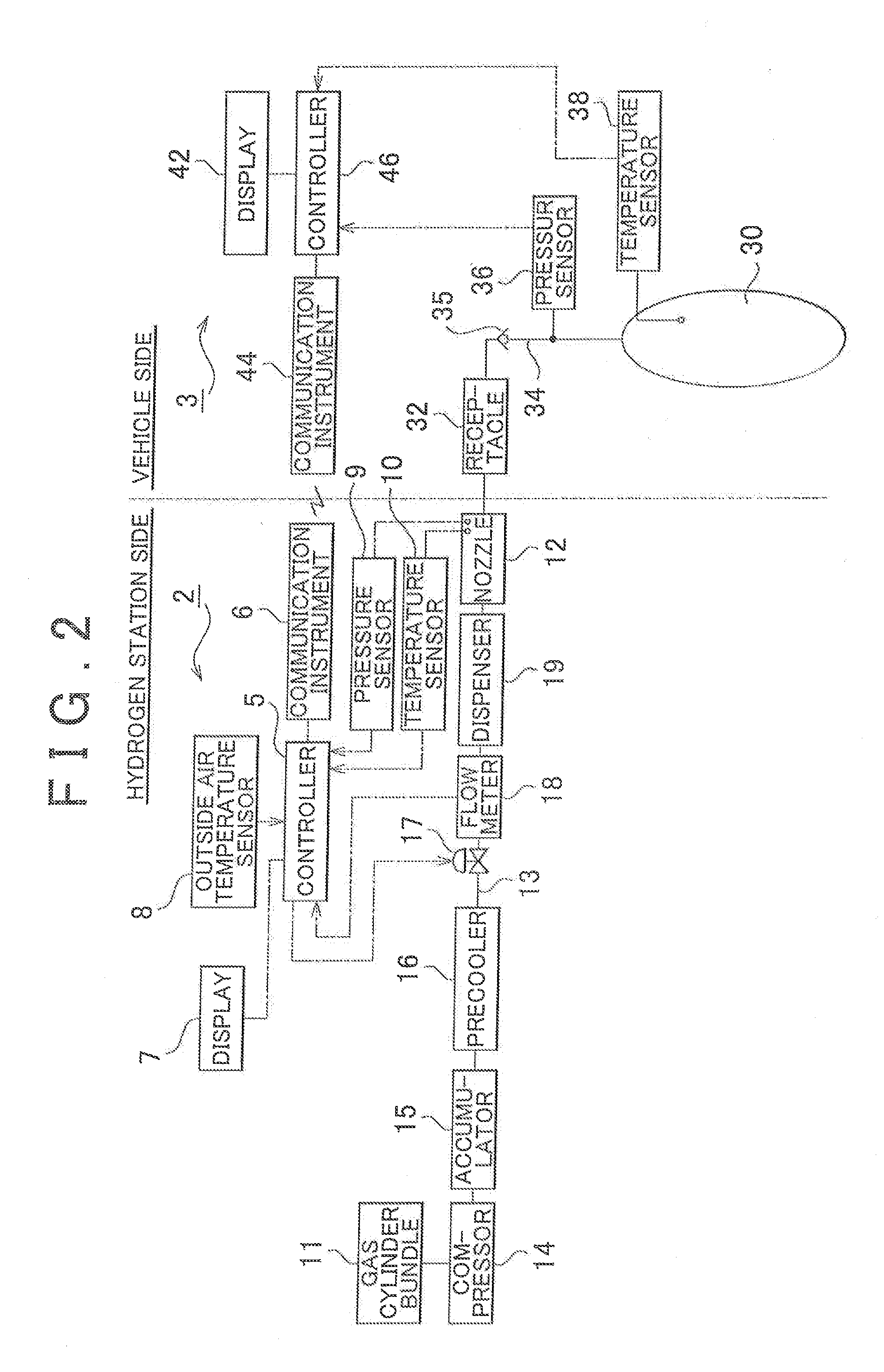
[0057]As shown in FIG. 2, the vehicle 3 includes a tank 30, a receptacle 32, a pressure sensor 36, a temperat...
PUM
| Property | Measurement | Unit |
|---|---|---|
| Temperature | aaaaa | aaaaa |
| Pressure | aaaaa | aaaaa |
| Flow rate | aaaaa | aaaaa |
Abstract
Description
Claims
Application Information