Eureka AIR delivers breakthrough ideas for toughest innovation challenges, trusted by R&D personnel around the world.

Mobile water treatment and resin transfer hub

a technology of resin transfer and water treatment, which is applied in water/sewage treatment by ion exchange, separation processes, filtration separation, etc., can solve the problems of significant expense of building a service centre, significant cost of moving the trailer, and significant cost of providing treated water at the site. , to achieve the effect of saving cos

Active Publication Date: 2013-02-14
BL TECH INC
View PDF9 Cites 5 Cited by
  • Summary
  • Abstract
  • Description
  • Claims
  • Application Information

AI Technical Summary

Benefits of technology

The system proposed in this patent helps reduce costs related to the transportation and operation of regenerated resin. This allows service centers to offer treatment to a larger service area, and reduces the overhead cost per treatment site. The system also reduces downtime at treatment sites while their resin is being regenerated. The resin transport vehicle, designed as an intermodal container, can store more resin in the same external dimensions compared to the treatment vehicle, and is less expensive. It is also easier to provide and ship. The resin transfer hub, which can be portable, can be moved if the location of distant treatment sites changes.

Problems solved by technology

However, building a service centre is a significant expense, on the order of several million dollars.
This in turn may require having treatment system trailers moving at times over very long distances.
For treatment systems using ion exchange resins that are returned from time to time to the service centre for regeneration, the cost of moving the trailers can add significantly to the cost of providing treated water at the site.
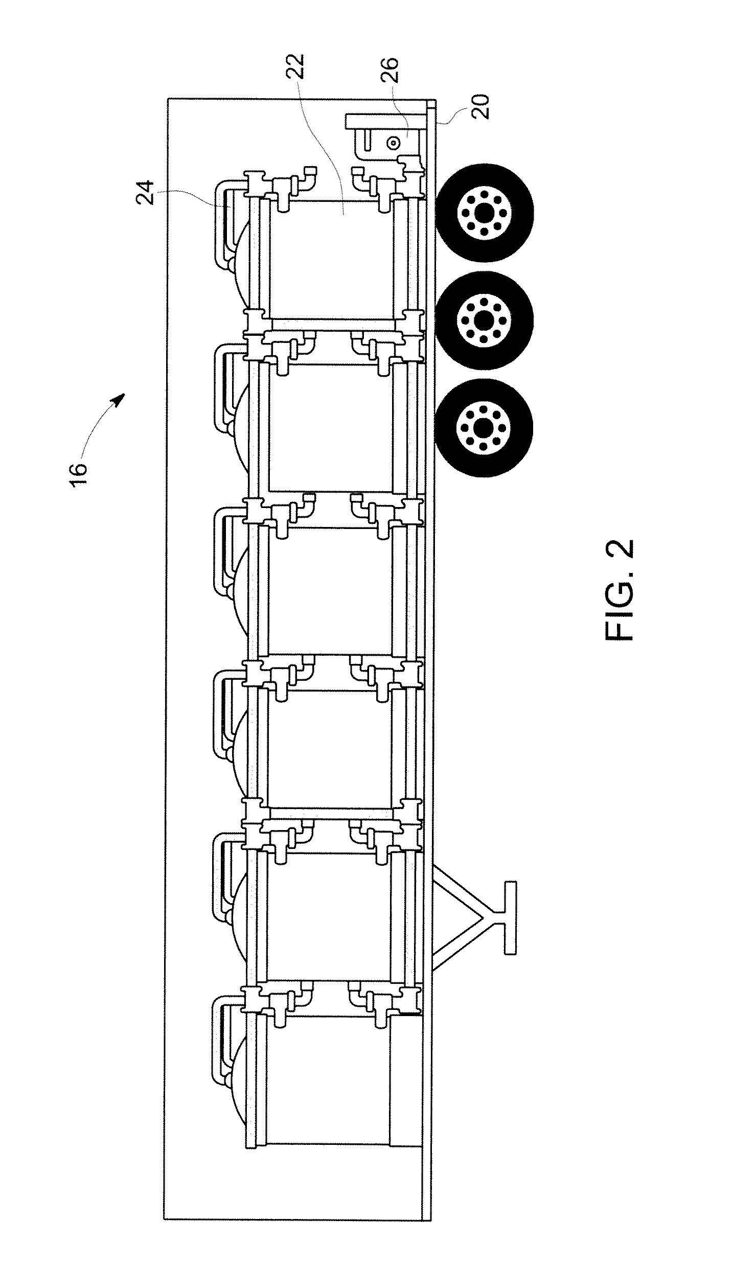
Savings in cost may result from one or more of the differences between the treatment vehicle and the resin transport vehicle.

Method used


Image

  • Mobile water treatment and resin transfer hub
  • Mobile water treatment and resin transfer hub
  • Mobile water treatment and resin transfer hub

Examples


Embodiment Construction

[0013]An example of a system and method for providing mobile or temporary water treatment involving ion exchange resin, and a resin transfer hub, will be described below.

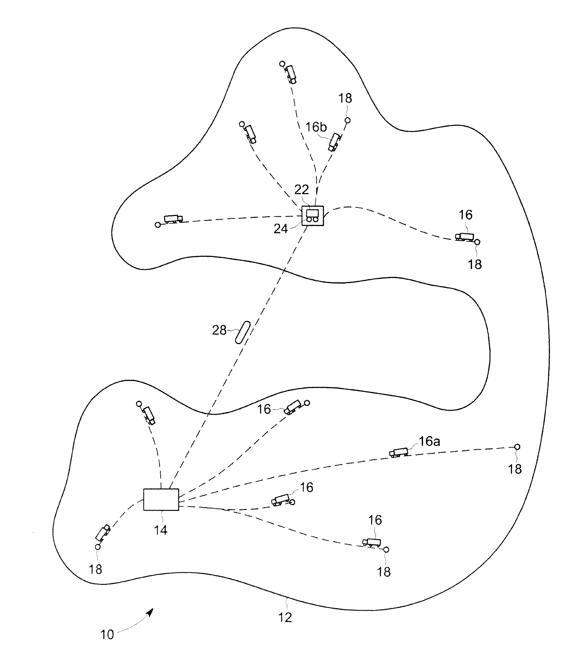
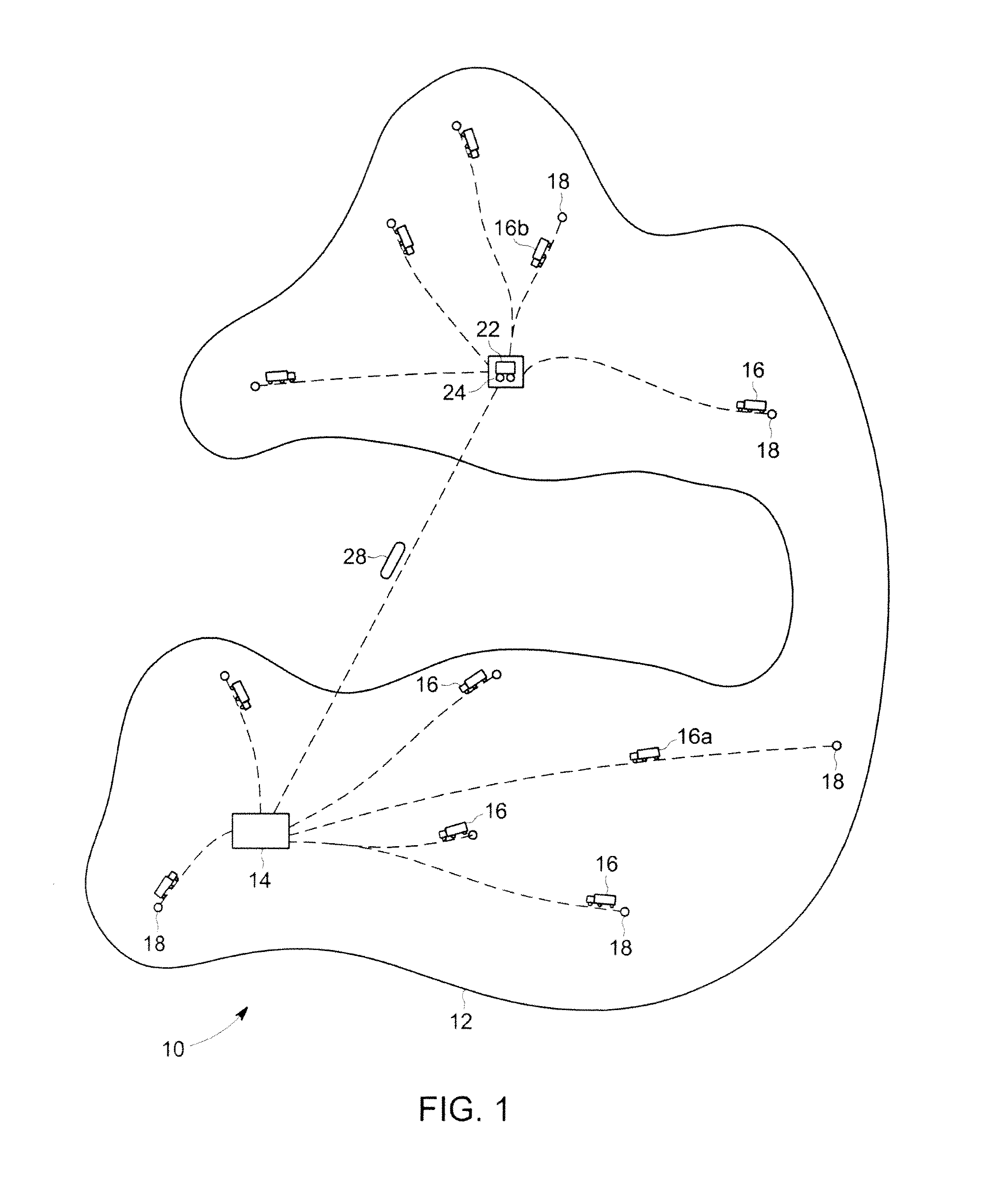
[0014]Referring to FIG. 1, a service area 10, represented by a large area of land 12, has a service centre 14 located in one part of it. The service centre includes equipment for regenerating spent ion exchange resins. At the service centre 14, resin beads needing regeneration are transferred from a vehicle carrying them to storage vessels where the beads can be regenerated. The regeneration process may include, for example, an air scrub, backwash, chemical regenerant application and deionized water rinse. The regenerated resin may also be tested or analyzed to determine the degree or quality of the regeneration. For mixed resin beds, there are also additional steps of separating the mixed bed before the resin is regenerated and, optionally, re-mixing the resins. The regenerated resin beads can then be transferred b...


PUM

PropertyMeasurementUnit
volumeaaaaaaaaaa
areaaaaaaaaaaa
timeaaaaaaaaaa

Abstract

A system and method for providing mobile or temporary water treatment involving ion exchange resins includes a service centre, one or more treatment vehicles, a resin transfer hub and one or more resin transport vehicles. The service centre can be used to regenerate one or more types of ion exchange resins. The treatment vehicle carries water treatment equipment including a tank holding ion exchange resin. The resin transfer hub facilitates moving resin between a treatment vehicle and a resin transport vehicle. The resin transport vehicle is adapted for carrying resin by one or more of land, sea and air between the resin forwarding centre and the service centre. In operation, a treatment vehicle brings resin requiring regeneration to the resin transfer hub, where it is emptied and then re-filled with regenerated resin. Resin requiring regeneration is transferred to a resin transport vehicle for transport to the service centre. The resin transport vehicle is re-filled there with regenerated resin, which is taken back to the resin transfer hub for transferred to a treatment vehicle.

Description

FIELD[0001]This specification relates to water treatment using ion exchange resins and to a system and method for providing mobile or temporary water treatment involving ion exchange resins.BACKGROUND[0002]In a mobile water treatment system, water treatment equipment is provided in a portable vehicle, such as a truck, trailer, skid or transport container, and delivered to a location where water treatment is required. Such mobile water treatment systems are used when it would be less economical to build a permanent treatment plant. For example, temporary water treatment may be required when a power plant is commissioned; when permanent water treatment plants are being repaired; for forestry or mining camps; or, to provide feed water for boilers that operate seasonally. In general, treated water may be required at a particular site for a period of time that may be up to several years but is still less that the lifetime of a permanent water treatment plant. Alternatively, treated water...

Claims


Application Information

Patent Timeline
Patent Type & Authority Applications(United States)
IPC IPC(8): B01J49/00C02F1/28
CPCB01J47/002B01J47/08B01J47/12B01J49/0082C02F1/42B01J47/04C02F2303/16B01J49/0017B01J49/0021B01J49/0086C02F2201/008B01J47/012B01J49/08B01J49/09B01J49/60B01J49/70B01J49/75B01J47/022C02F2103/007
Inventor PARKE, ANDREW
Owner BL TECH INC
Why Eureka
Eureka Blog
Learn More