
Method, device and a computer program for manufacturing a pre-insulated skeleton framing segment

Active Publication Date: 2013-02-14
MAC INVESTMENTS BV
View PDF5 Cites 20 Cited by
  • Summary
  • Abstract
  • Description
  • Claims
  • Application Information

AI Technical Summary

Benefits of technology

The invention provides a method for making a pre-insulated skeleton framing segment for buildings of various sizes that is less prone to errors, requires less labor, and reduces waste of insulation material.

Problems solved by technology

A drawback of this method is that it is highly labour intensive, that the openings in the boards have to be made in visible positions, and that a great deal of insulating material is wasted in most cases.
However, a disadvantage of this method is that the wall panels are often poorly insulated and that there is a lot of cutting waste of the insulation material and that the method is labour intensive.
A disadvantage of this method is that it is highly labour intensive and susceptible to errors.

Method used


Image

  • Method, device and a computer program for manufacturing a pre-insulated skeleton framing segment
  • Method, device and a computer program for manufacturing a pre-insulated skeleton framing segment
  • Method, device and a computer program for manufacturing a pre-insulated skeleton framing segment

Examples


example 1

Device for Method with Closed Assembly

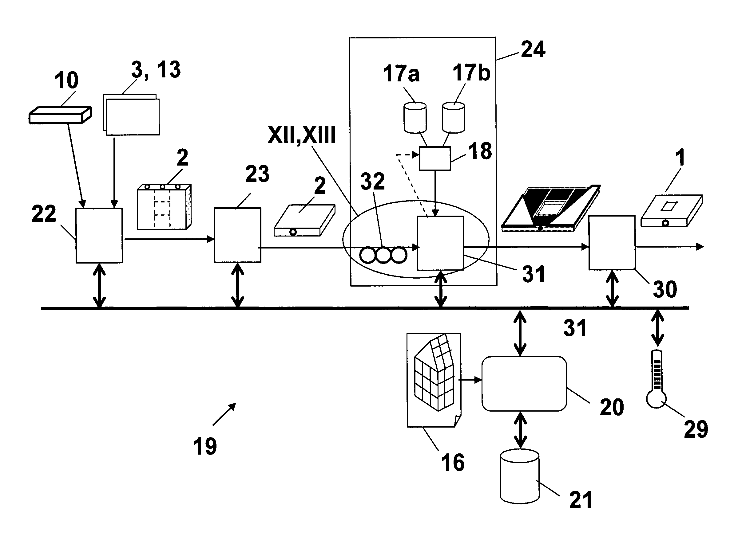
[0220]FIG. 11A and FIG. 11B show a block diagram of a first preferred embodiment of a device 19, whereby a closed assembly 2 is provided as an intermediate product to the filling unit 24. The difference between FIG. 11A and FIG. 11B is that the data carrier 40 fitted to the assembly 2 in FIG. 11A itself contains the data for determining the required raw materials, whereas they have to be retrieved from the database 21 in FIG. 11B. Unless explicitly indicated otherwise, all that is described for FIG. 11A also applies to FIG. 11B, and vice versa. FIG. 11 refers to both FIG. 11A and FIG. 11B.

[0221]FIGS. 11-14 show a fully automatic and computer-controlled embodiment of the device 19, although this is not necessary for the invention. Certain parts may also be controlled manually, such as e.g. the insertion of one or more assemblies 2 in the press 31, as will be described further. Also note that the assembly unit 22 is not necessarily part of the dev...

example 2

Device for Method with Half-Open Assembly

[0244]FIGS. 15A and 15B show two variants of a block diagram of a second preferred embodiment of a device 19 according to the invention. The difference between the device in FIGS. 15A and 15B is again the fact that in the one case the data carrier 40 itself contains the data of assembly 2 (FIG. 15A), whilst they must be retrieved from the database 21 in FIG. 15B. This block diagram resembles that of FIG. 11 very closely, therefore only the most significant differences will be described.

[0245]On the left-hand side of FIG. 15 an assembly unit 22 is shown, similar to that in FIG. 11, except that this one manufactures a half-open assembly 2, with a first flat panel 3 secured to a frame 4. The assembly 2 may optionally be tilted or turned over by positioning means 23 (e.g. a “butterfly turning table”). Optionally the assembly 2 may be temporarily stocked in a buffer zone (not shown).

[0246]In the centre of FIG. 15 an assembly 2 is received and fed ...


PUM

PropertyMeasurementUnit
Temperatureaaaaaaaaaa
Thicknessaaaaaaaaaa
Forceaaaaaaaaaa

Abstract

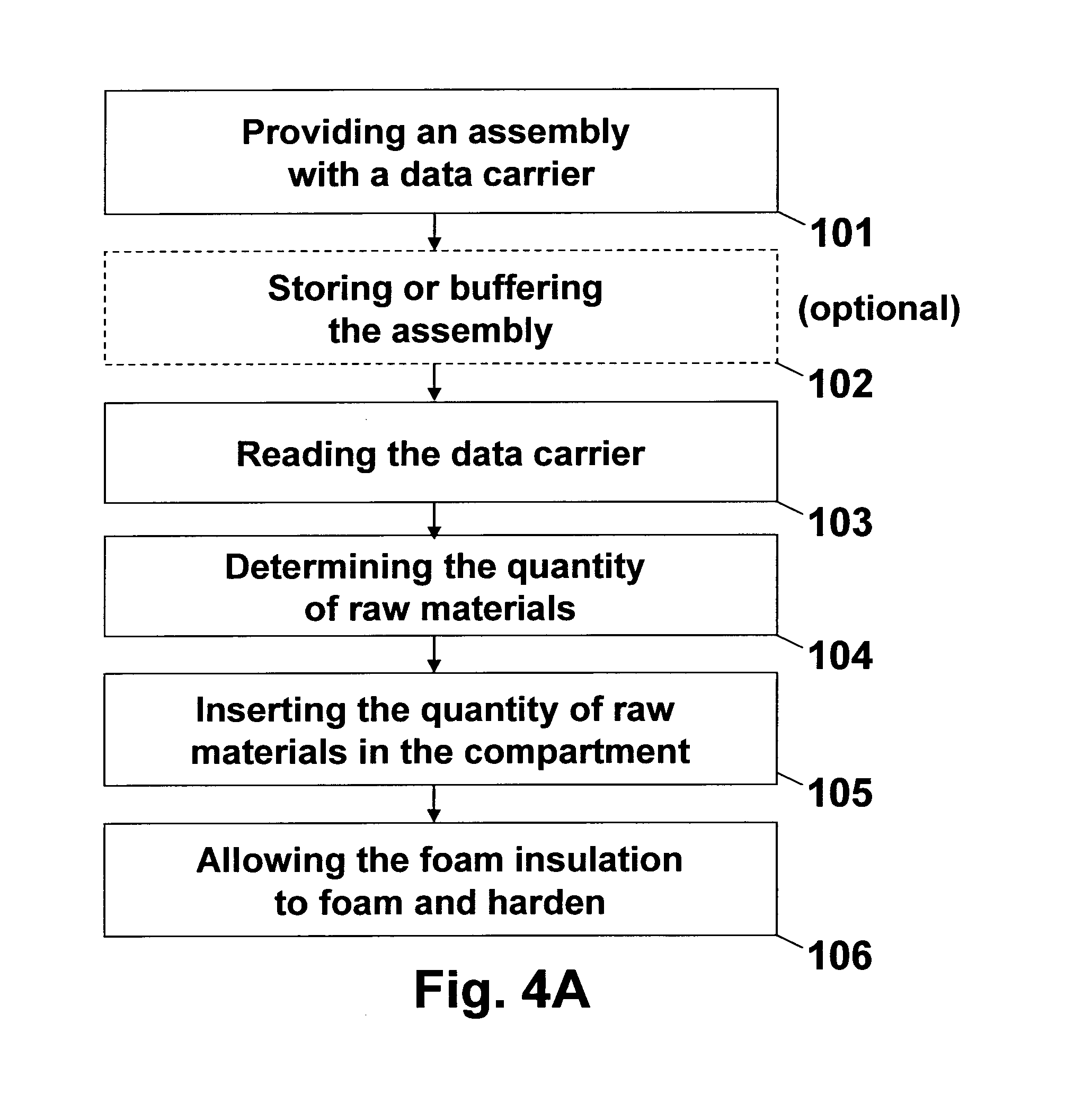
A method, a device and a computer program for manufacturing a pre-insulated skeleton framing segment (1) for a building to be constructed, wherein an assembly (2) with a hollow space (14) is provided, to which a data carrier (40) is fitted including data from which a quantity of raw materials required for forming a foam insulation layer of a thickness (15) in the hollow space (14) can be determined, which quantity is calculated, and which raw materials are inserted in the hollow space (14), and foam and harden there during a period (T).

Description

DOMAIN OF THE INVENTION[0001]The invention relates to a method for manufacturing a pre-insulated skeleton framing segment for a building to be constructed, more specifically a skeleton framing segment which is at least partially filled with a foam insulation layer during its production.[0002]The invention also relates to a pre-insulated skeleton framing segment manufactured according to this method and to a building which comprises these skeleton framing segments.[0003]The invention also relates to a device and a computer program provided for carrying out this method.BACKGROUND ART[0004]For the construction of skeleton apartments a method is known for producing prefab wall panels of standard dimensions which are secured to each other on site. These panels generally consist of two parallel wooden boards which are secured to a frame (also called skeleton or framework) located between the two boards. To increase the insulation of the apartment, these wall panels are generally insulated...

Claims


Application Information

Patent Timeline
IPC IPC(8): B29C44/18B29D21/04
CPCB29C44/1228B29C44/186B29C44/60E04C2/386B29L2031/10E04C2/296B29K2075/00B29K2305/00B29K2311/14B29K2995/0015E04B1/18B05B3/00B05B12/02B29C39/10B29C39/44B29C44/025B29C44/10B29C44/1276B29C44/128B29C44/18B29C69/001B29K2105/04B29L2009/00E04C2/205E04C2/38E04C2/388E04C2/52
Inventor ARNAUTS, DIRK
Owner MAC INVESTMENTS BV
Learn More