
Liquid crystal display device

a liquid crystal display and display screen technology, applied in optics, instruments, optical elements, etc., can solve the problems of affecting the color productivity and red chromaticity of the image, the crystal response speed is degraded, and the difficulty in sufficiently warm the liquid crystal panel, so as to reduce the reaction speed of the liquid crystal and enhance color productivity and red chromaticity.

Inactive Publication Date: 2013-02-14
SHARP KK
View PDF2 Cites 0 Cited by
  • Summary
  • Abstract
  • Description
  • Claims
  • Application Information

AI Technical Summary

Benefits of technology

The present invention allows for a liquid crystal display device to use a white LED lamp as a light source while reducing degradation of liquid crystal response speed and improving color productivity and red chromaticity. This is achieved without using a dedicated color filter for the white LED lamp.

Problems solved by technology

However, the white LED lamp generates less heat than the CCFL, and thus, if the white LED lamp is used as a light source, it is sometimes difficult to sufficiently warm the liquid crystal panel.
In such a case, the liquid crystal response speed is degraded, which may invite degradation of the image display quality.
In particular, in a case of a liquid crystal display device using a large-size liquid crystal panel, the liquid crystal panel is prone to in-plane temperature distribution.
In a case where the white LED lamp is used in such an edge light type liquid crystal display device, insufficient warming of the liquid crystal panel and occurrence of the distribution of the response speed may degrade the display quality of images still more than in a case where the white LED lamp is used as a light source in a direct type liquid crystal display device.
Furthermore, in the case of a liquid crystal display device using a white LED lamp as a backlight light source, red chromaticity may be degraded due to light emission characteristics of the white LED lamp.

Method used


Image

  • Liquid crystal display device
  • Liquid crystal display device
  • Liquid crystal display device

Examples


Embodiment Construction

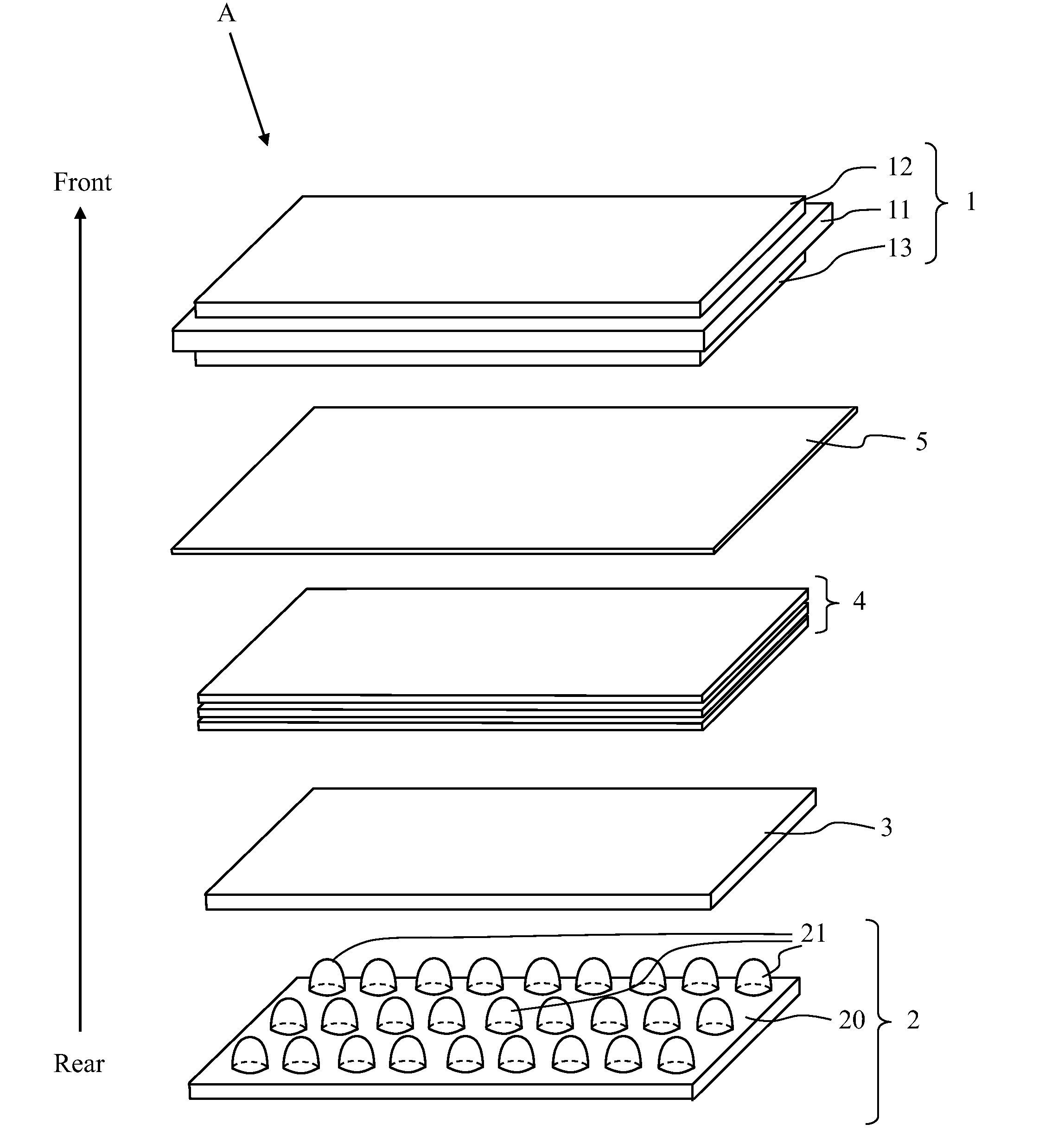
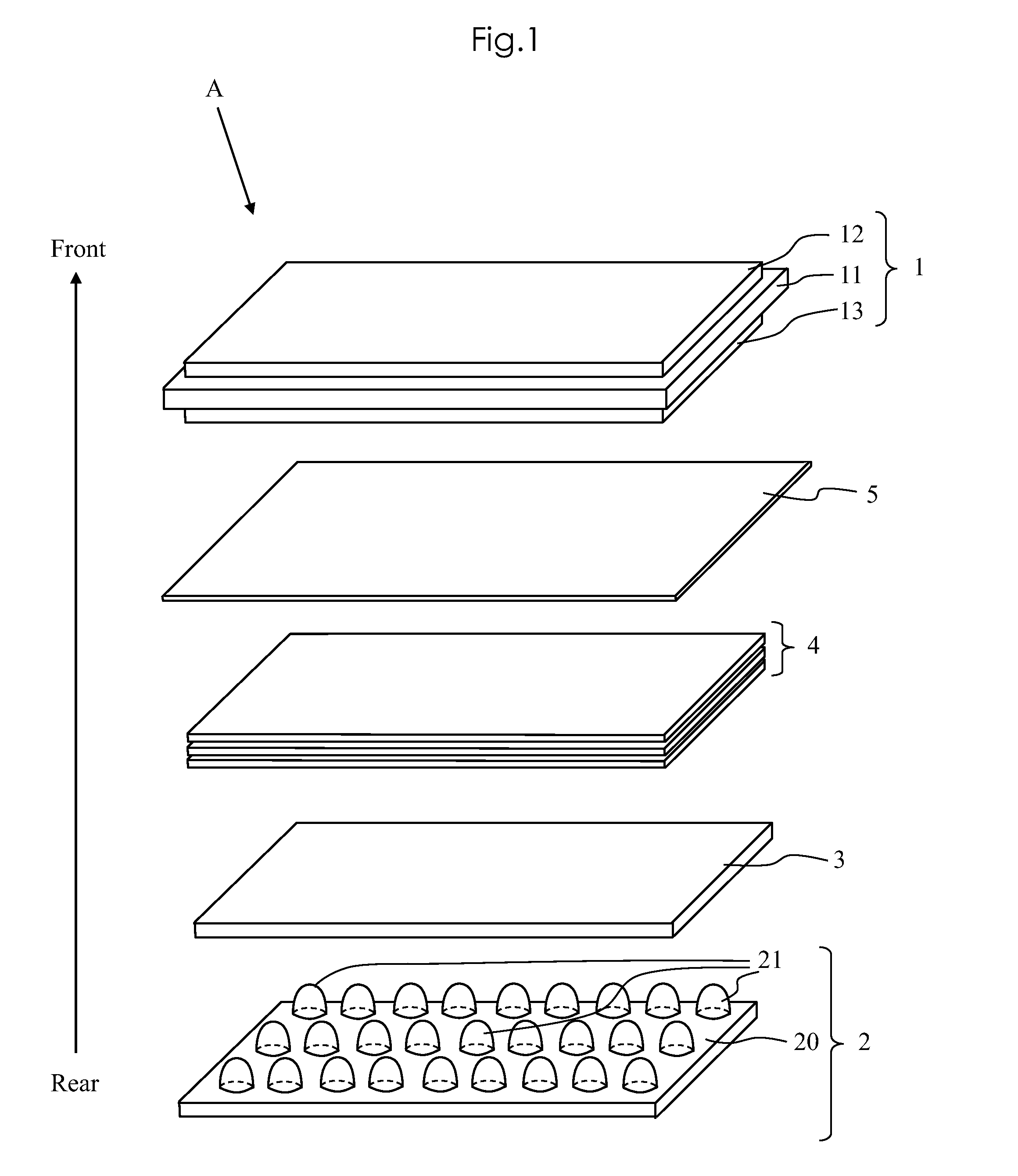
[0029]Embodiments of the present invention will be described below with reference to the accompanying drawings. FIG. 1 is an exploded perspective view of a liquid crystal display device according to the present invention. As shown in FIG. 1, a liquid crystal display A is one that is provided with a direct type backlight. The liquid crystal display device A includes a liquid crystal display panel 1 and a backlight unit 2 disposed at a rear side of the liquid crystal display panel 1.

[0030]The liquid crystal display panel 1 has a liquid crystal panel 11 in which liquid crystal is sealed, a polarization plate 12 which is put on a front surface (a side closer to a viewer) of the liquid crystal panel 11, and a polarizing plate 13 which is put on a rear surface (a side closer to the backlight unit 2) of the liquid crystal panel 11. The liquid crystal panel 11 includes an array substrate which includes a switching element such as a TFT (thin film transistor), a counter substrate which is di...


PUM

PropertyMeasurementUnit
wavelengthaaaaaaaaaa

Abstract

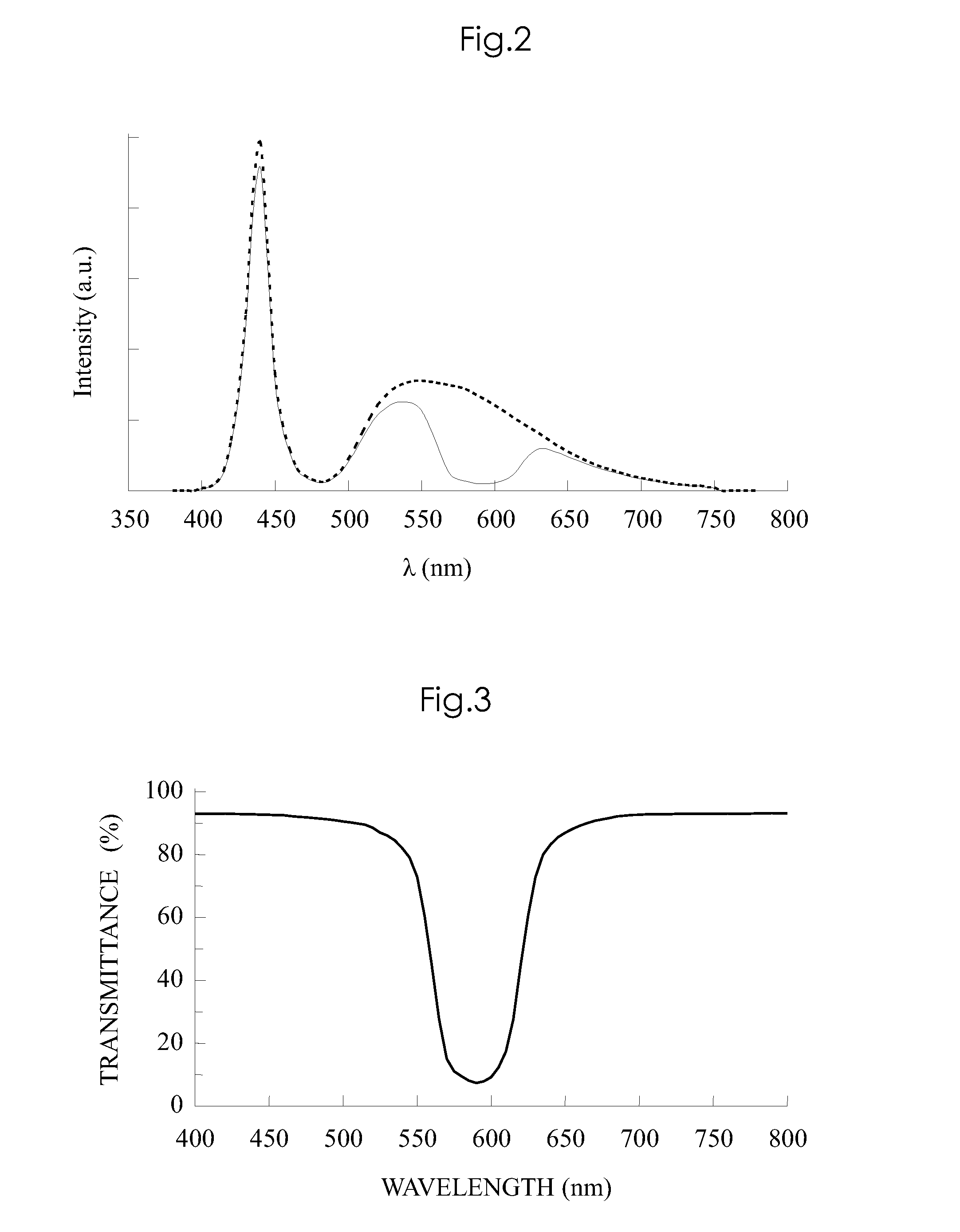
In a liquid crystal display device which uses a white LED as the light source, in order to avoid / suppress the reduction in the speed of response of the liquid crystal while increasing the color reproducibility and red chromaticity without the use of a special purpose color filter, a band cut filter which absorbs the wavelength component neighboring orange in light that is transmitted is provided between the liquid crystal display and the backlight unit.

Description

TECHNICAL FIELD[0001]The present invention relates to a liquid crystal display device using a white LED lamp as a backlight light source.BACKGROUND ART[0002]As a light source for a backlight unit of a liquid crystal display device, a white LED lamp, which emits white light, has been increasingly adopted instead of a conventional CCFL (cold cathode fluorescent lamp). In contrast with the conventional CCFL, the white LED lamp is advantageous in, for example, that no mercury is used therein, that it does not need to be provided with a high voltage circuit for electric discharge nor means for cutting noise from the circuit, and that it is able to be made compact easily.[0003]On the other hand, in a liquid crystal display device that uses a conventional CCFL as a light source, heat generated by the CCFL is used to warm a liquid crystal panel. By warming the liquid crystal panel, it is possible to increase the liquid crystal response speed, to thereby reduce degradation of image display q...

Claims


Application Information

Patent Timeline
Patent Type & Authority Applications(United States)
IPC IPC(8): G02F1/13357G02F1/1335
CPCG02B5/22G02F2001/133624G02F1/133609G02F1/133603G02F1/133624
Inventor SUGIHARA, TOSHINORI
Owner SHARP KK
Learn More