Image display

a technology of image display and display device, which is applied in the field of image display device, can solve the problems of so-called color breakup, increase in the cost of components significant deterioration of light utilization efficiency, so as to reduce the response speed required of spatial light modulator, reduce the light utilization efficiency, and improve the definition

Inactive Publication Date: 2006-05-09
SONY CORP
View PDF19 Cites 6 Cited by
  • Summary
  • Abstract
  • Description
  • Claims
  • Application Information

AI Technical Summary

Benefits of technology

[0022]According to this invention, by combining the advantages of the first and second systems, it is possible to display a color image with one spatial light modulator and to solve the problem of the first system, that is, low definition, and the problems of the second system, that is, color breakup and low light utilization efficiency.
[0023]In the image display device according to this invention, since one color image is formed physically by two basic color pixels, the definition can be improved. As the spatial light modulator only needs to perform two-color time-division switching display, the response speed required of the spatial light modulator is reduced. Therefore, the color breakup phenomenon can be relaxed and the light utilization efficiency can be improved.
[0024]According to this invention, by combining the advantages of the first and fourth system, it is possible to display a color image with two spatial light modulators. As the spatial light modulators, which time-divisionally modulates illuminating light of two colors in the fourth system, are spatially arranged on two basic color pixels as in the first system, the problems such as color breakup and lowering of light utilization efficiency due to employment of the “field sequential system”, and the problems due to the need to switch the color of the illuminating light can be solved.

Problems solved by technology

That is, a problem of so-called color breakup occurs.
This means that if an illuminating light source for emitting light simultaneously over all the range such as a lamp light source is used, only a part of emission spectrum of the light source can be effectively used at arbitrary timing and therefore the light utilization efficiency is significantly deteriorated.
In the third system, though the problems of the above-described first and second system do not occur, there are problems such as increase in the cost of components of the spatial light modulators due to the use of the three spatial light modulators, complexity of adjustment for alignment of relative positions of the three spatial light modulators, increase in the cost of components of the color combination system for the three colors, and increase in the size of the device.
There is also a problem of poor reliability in positional deviation of the spatial light modulators with respect to each other.
Moreover, in the case where the device is constructed as a projection-type image display device, there is a problem of increase in F-number of a projection optical system due to increase of back focusing to the projection optical system.
This leads to increase in the size of the projection optical system and increase in the manufacturing cost.
However, it cannot solve the problems of the second system, that is, the occurrence of color breakup in the case the response speed of the color switching element is not sufficiently high and lowering of the light utilization efficiency due to the employment of the “field sequential system”, and the problems due to the need to switch the color of illuminating light.

Method used


Image

  • Image display
  • Image display
  • Image display

Examples


first embodiment

[0050]As a first embodiment of an image display device according to this invention, an example in which this invention is applied to a two-plate projection-type image display device will be described.

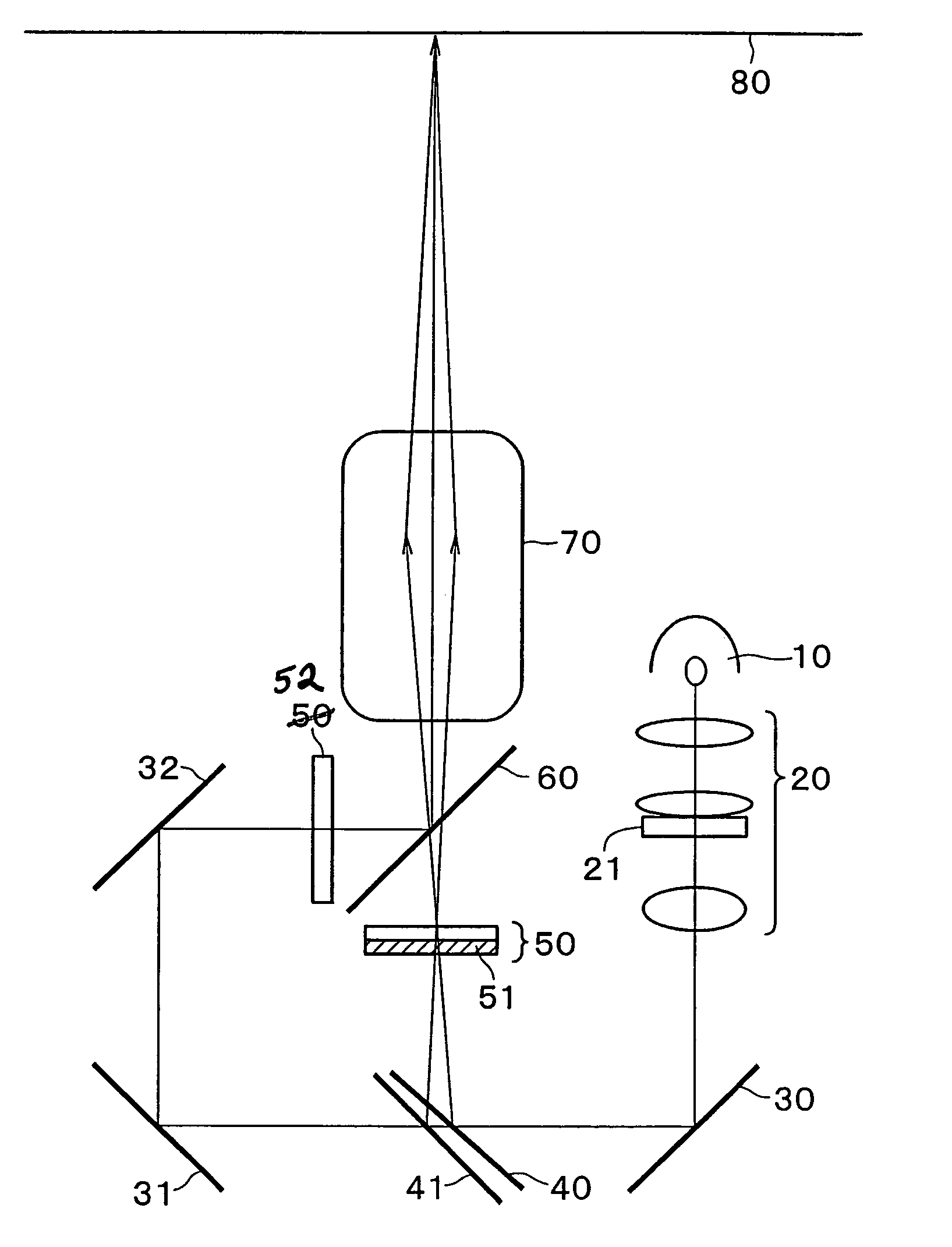
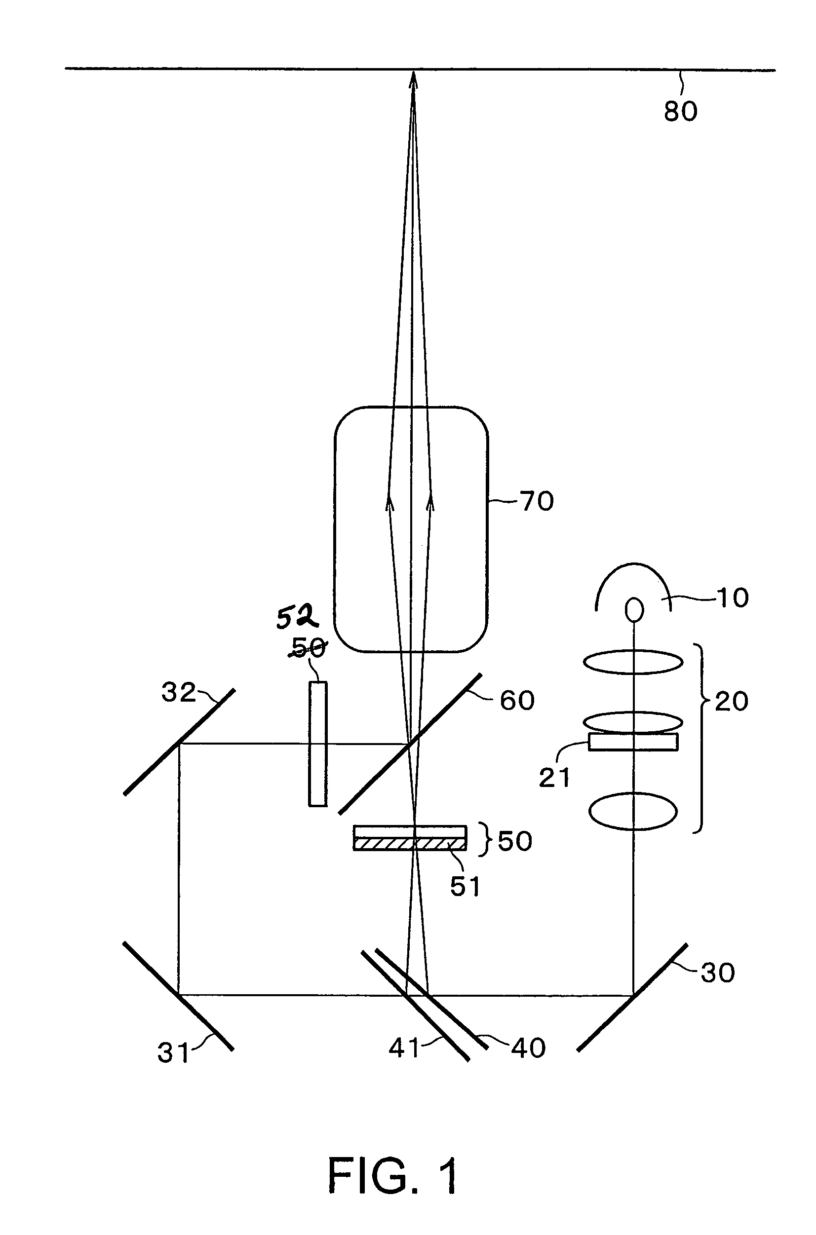
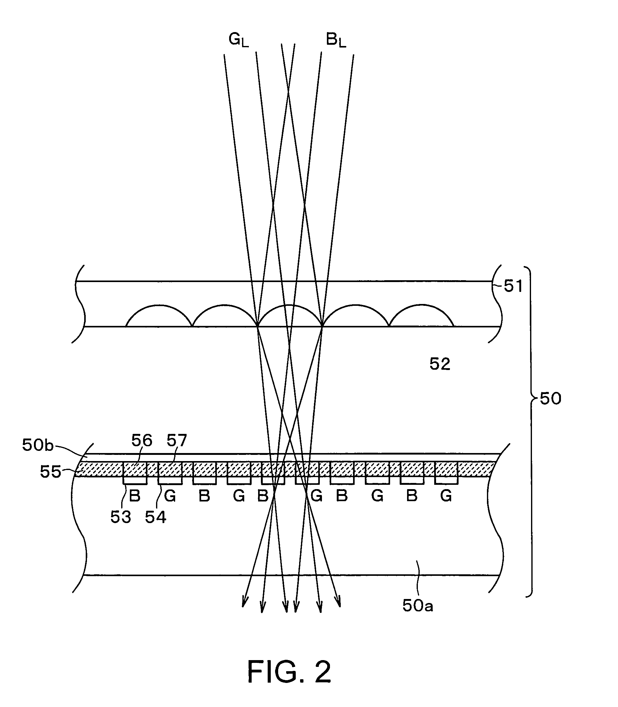
[0051]The two-plate projection-type image display device has transmission liquid crystal elements 50, 52 as spatial light modulators, a dichroic mirror 60 as color combination means, dichroic mirrors 40, 41 as color separation means to the two transmission liquid crystal elements 50, 52, and the dichroic mirrors 40, 41 and a microlens array 51 as color separation and condensation means to the one transmission liquid crystal element, as shown in FIG. 1.

[0052]In the two-plate projection-type image display device, illuminating light emitted from a UHP lamp light source 10 as an illuminating light source becomes incident on an illuminating optical system 20 having functions such as correction of the cross-sectional shape of luminous flux, equalization of intensity, and control of divergence...

second embodiment

[0062]As a second embodiment of the image display device according to this invention, an example in which this invention is applied to a two-plate projection-type image display device will be described.

[0063]The two-plate projection-type image display device in the second embodiment has transmission liquid crystal elements 50, 52 as spatial light modulators, a polarized light beam splitter 61 as color combination means, dichroic mirrors 40, 41 as color separation means for the two transmission liquid crystal elements 50, 52, and the dichroic mirrors 40, 41 and a microlens array 51 as color separation and condensation means to the one transmission liquid crystal element 50, as shown in FIG. 5.

[0064]First, illuminating light emitted from a UHP lamp light source 10 constituting an illuminating light source together with a red LED light source 11, which will be described later, becomes incident on an illuminating optical system 20 having functions such as correction of the cross-section...

third embodiment

[0076]As a third embodiment of the image display device according to this invention, an example in which this invention is applied to a two-plate projection-type image display device will be described.

[0077]The two-plate projection-type image display device in the third embodiment has reflection liquid crystal spatial light modulators 101, 102 as spatial light modulators, a polarized light beam splitter 140 and specific wavelength range linear polarization rotation means (multilayer phase difference filter) 120 as color combination means, dichroic mirrors 40, 41 as color separation means for the two reflection liquid crystal spatial light modulators 101, 102, and a transmission polarization-selective holographic optical element 100 as color separation and condensation means to the one reflection liquid crystal spatial light modulator, as shown in FIG. 9.

[0078]In this two-plate projection-type image display device, first, illuminating light emitted from a UHP lamp light source 10 as ...


PUM

PropertyMeasurementUnit
switching frequencyaaaaaaaaaa
wavelength rangeaaaaaaaaaa
thicknessaaaaaaaaaa

Abstract

This invention is an image display device for performing color display of an image using two spatial light modulators. The image display device has a first spatial light modulator (52) for modulating a first wavelength range component of illuminating light from an illuminating light source (10), dichroic mirrors (40), (41) for separating second and third wavelength range components of the illuminating light and condensing the respective wavelength range components, a second spatial light modulator (50) for modulating the second and third wavelength range components, and a dichroic mirror (60) for combining modulated light emitted from the first and second spatial light modulators (52), (50).

Description

BACKGROUND OF THE INVENTION[0001]This invention relates to an image display device, and particularly to a projection-type image display device and a virtual image display device.BACKGROUND ART[0002]Conventionally, with respect to an image display device such as a projection-type image display device or a virtual image display device using a spatial light modulator, the following proposals have been in order to realize color image display.[0003](1) One spatial light modulator is used and pixels for R (red), G (green) and B (blue), respectively, are spatially arranged in the spatial light modulator. Color image display is realized by using at least these three basic color pixels as a set and making each color pixel smaller than a size that can be recognized with the spatial resolution of human eyes.[0004]Systems for this include a system in which a color filter is provided for each pixel, a color filterless system using a dichroic mirror and a microlens array, for example, as describe...

Claims


Application Information

Patent Timeline
Patent Type & Authority Patents(United States)
IPC IPC(8): G02B5/20G02B27/10G02F1/1335G03B21/00H04N5/74G02B5/08G02B3/00G02B5/18G02B5/30G02B5/32G02F1/13G02F1/13357G03B33/12
CPCH04N9/3167H04N9/3105G03B21/00G02F1/13362G02F2001/133623G03B21/005G03B21/006G02F1/133623H04N9/30
Inventor MUKAWA, HIROSHITANAKA, YOSHINORI
Owner SONY CORP
Why Eureka
Try Eureka