Electrochromic element, method of driving the same, an optical filter, lens unit, image pick-up device and window material

a technology of electrochromic elements and optical filters, applied in non-linear optics, instruments, optics, etc., can solve the problems of increasing power consumption, insufficient decoloring due to charge imbalance, and reducing response speed, so as to reduce power consumption, reduce response speed, and eliminate insufficient decoloration

Active Publication Date: 2016-12-08
CANON KK
View PDF2 Cites 6 Cited by
  • Summary
  • Abstract
  • Description
  • Claims
  • Application Information

AI Technical Summary

Benefits of technology

[0006]Accordingly, it is an object of the present invention to provide an EC element that can eliminate insufficient decoloring due to charge imbalance without being accompanied by increased power consumption and by reduced response speed, and that is excellent in reproducing a spectrum in coloring operation is eliminated.

Problems solved by technology

In such an EC element, suppression of change in optical characteristics as time progresses is one of the biggest challenges.
In particular, in an EC element called a complementary EC element that uses an anodic EC material and a cathodic EC material, insufficient decoloring due to charge imbalance is a problem.
As a result, there are problems in that, compared to a case in which the redox buffers are not used, a current that does not contribute to the coloring unnecessarily flows to increase the power consumption and to reduce the response speed.
However the charge imbalance between the display electrodes is not corrected, and thus, the colored form ratio of the anodic EC material / the cathodic EC material cannot be corrected.

Method used


Image

  • Electrochromic element, method of driving the same, an optical filter, lens unit, image pick-up device and window material
  • Electrochromic element, method of driving the same, an optical filter, lens unit, image pick-up device and window material
  • Electrochromic element, method of driving the same, an optical filter, lens unit, image pick-up device and window material

Examples


synthesis example 1

Synthesis of Compound 1

[0123]A synthesis example of Compound 1 serving as the anodic EC material is described below.

[0124]In a 50-milliliter reaction vessel, 500 mg (1.67 mmol) of XX-1 (2,5-dibromoethylene dioxythiophene) and 1.05 g (5.0 mmol) of 2-isopropoxy-6-methoxyphenylboronic acid were mixed in a mixed solvent of toluene / tetrahydrofuran (10 ml / 5 ml), and nitrogen was used to remove dissolved oxygen.

[0125]Next, 19 mg (0.083 mmol) of Pd (OAc)2, 89 mg (0.22 mmol) of 2-dicyclohexylphosphino-2′,6′-dimethoxybiphenyl (S-Phos), and 1.92 g (8.35 mmol) of tripotassium phosphate were added thereto under a nitrogen atmosphere, and the reaction was performed for 7 hours while being heated to reflux at 110° C.

[0126]The reaction solution was cooled to room temperature, and then concentrated under reduced pressure, and separated and purified by silica gel chromatography (mobile phase: hexane / ethyl acetate=4 / 3) to provide Compound 1 as white solid powder (420 mg, yield: 54%).

[0127]Measurement ...

synthesis example 2

Synthesis of Compound 2

[0129]Compound 2 serving as the cathodic EC material was synthesized based on the document of Cinnsealach et al. (Solar Energy Materials and Solar Cells Vol. 57 (1999) 107-125).

synthesis example 3

Synthesis of Compound 3

[0130]Compound 3 serving as the anodic EC material was synthesized based on the document of Cummins et al. (Journal of Physical Chemistry B 104 (2000) 11449-11459).


PUM

PropertyMeasurementUnit
decoloring voltageaaaaaaaaaa
transmittanceaaaaaaaaaa

Abstract

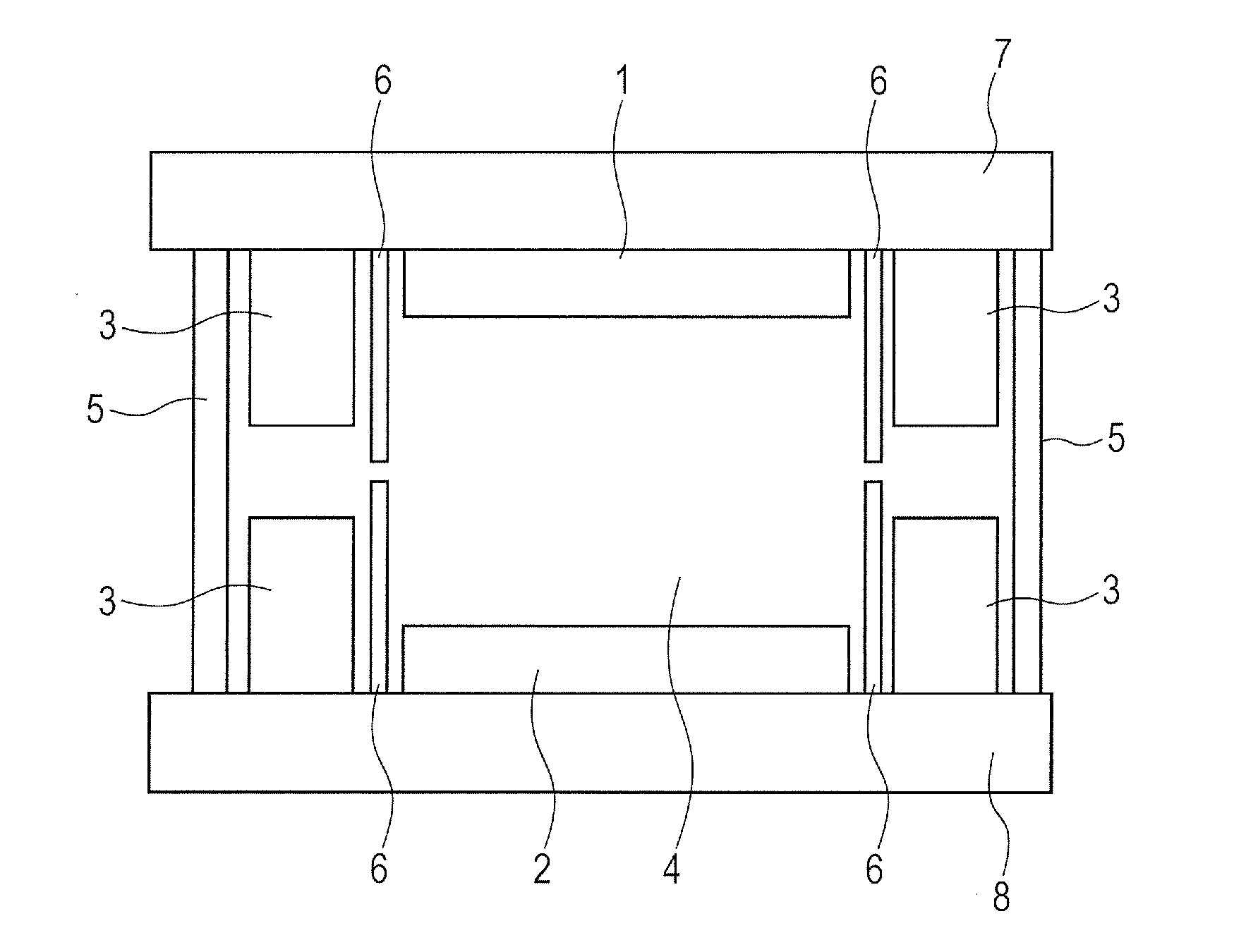
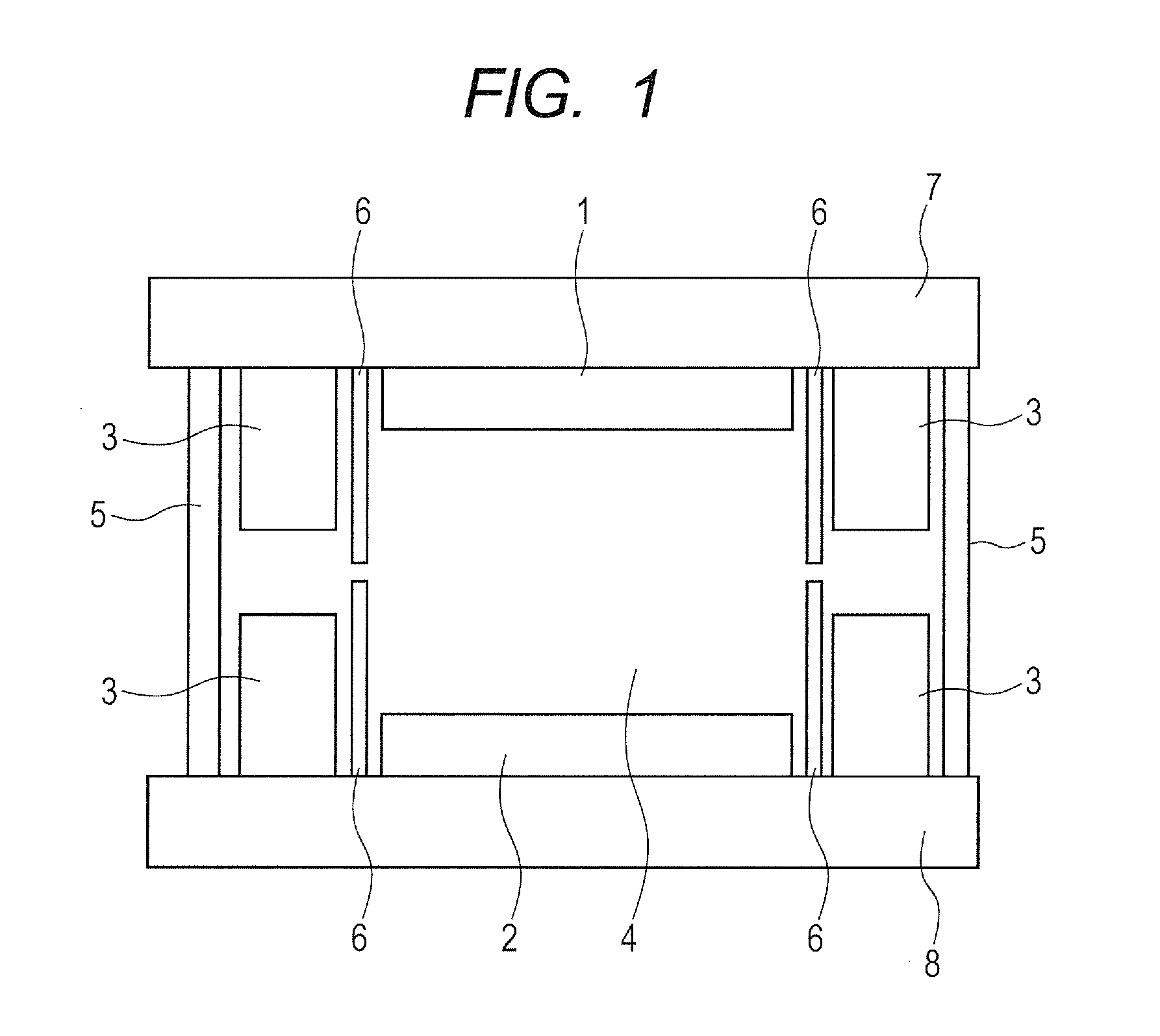
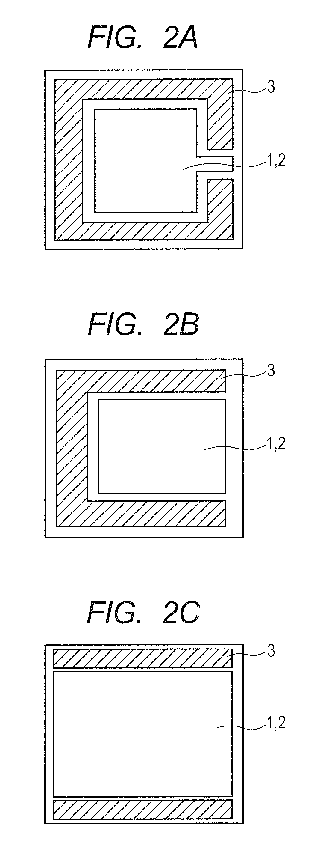
Provided is an electrochromic element, including: a first electrode and a second electrode, at least one of the first electrode and the second electrode being transparent; a third electrode; and an electrolyte, an anodic organic electrochromic material, and a cathodic organic electrochromic material that are arranged between the first electrode and the second electrode, in which the third electrode is electrically connectable to at least one of the first electrode and the second electrode via the electrolyte, and in which the third electrode has an effective area that is larger than an effective area of the first electrode and an effective area of the second electrode.

Description

BACKGROUND OF THE INVENTIONField of the Invention[0001]The present invention relates to an electrochromic element and a method of driving the same, and further, to an optical filter, a lens unit, an image pickup apparatus, and a window member using the electrochromic element.Description of the Related Art[0002]An electrochromic (hereinafter sometimes abbreviated as “EC”) element that uses an EC material as a substance that undergoes changes in optical absorption properties (absorption wavelength and absorbance) through an electrochemical redox reaction is applied to a display apparatus, a variable reflectance mirror, a variable transmission window, and the like. In such an EC element, suppression of change in optical characteristics as time progresses is one of the biggest challenges. In particular, in an EC element called a complementary EC element that uses an anodic EC material and a cathodic EC material, insufficient decoloring due to charge imbalance is a problem. Note that, th...

Claims


Application Information

Patent Timeline
Patent Type & Authority Applications(United States)
IPC IPC(8): G02F1/155G02F1/163G02F1/153G02F1/1503
CPCG02F1/155G02F1/1533G02F2001/1536G02F2001/1502G02F2001/1515G02F1/163G02F1/1503
Inventor KUBO, WATARUMIYAZAKI, KAZUYA
Owner CANON KK
Why Eureka
Try Eureka