
Apparatus for manufacturing light guide film

a technology of light guide film and apparatus, which is applied in the direction of manufacturing tools, instruments, dough shaping, etc., can solve the problems of increasing the cost accordingly, raising the yield and capacity problem, and raising the problem of problems, etc., and achieves the effect of low efficiency and high cos

Active Publication Date: 2013-02-14
SVG TECH GRP CO LTD +1
View PDF8 Cites 5 Cited by
  • Summary
  • Abstract
  • Description
  • Claims
  • Application Information

AI Technical Summary

Benefits of technology

The present invention provides a roll-to-roll apparatus for manufacturing a light guide film, which overcomes the inefficiency and high cost of conventional flat pressing devices and the inability of conventional injection molding devices to manufacture large-sized super slim light guide films. The method utilizes roll-to-roll nano-scaled press printing, which increases manufacturing efficiency and consistency with a yield rate greater than 95%. Compared to conventional methods, the roll-to-roll apparatus is easier to control and requires lower temperatures and environments.

Problems solved by technology

Due to the reduction of the thickness, some problems may be raised during manufacturing of the light guide plate.
However, there is a strict surface quality requirement by the super slim light guide film.
For the conventional injection molding, yield and capacity problems may be raised to increase the cost accordingly if the light guide film with high quality may be manufactured.
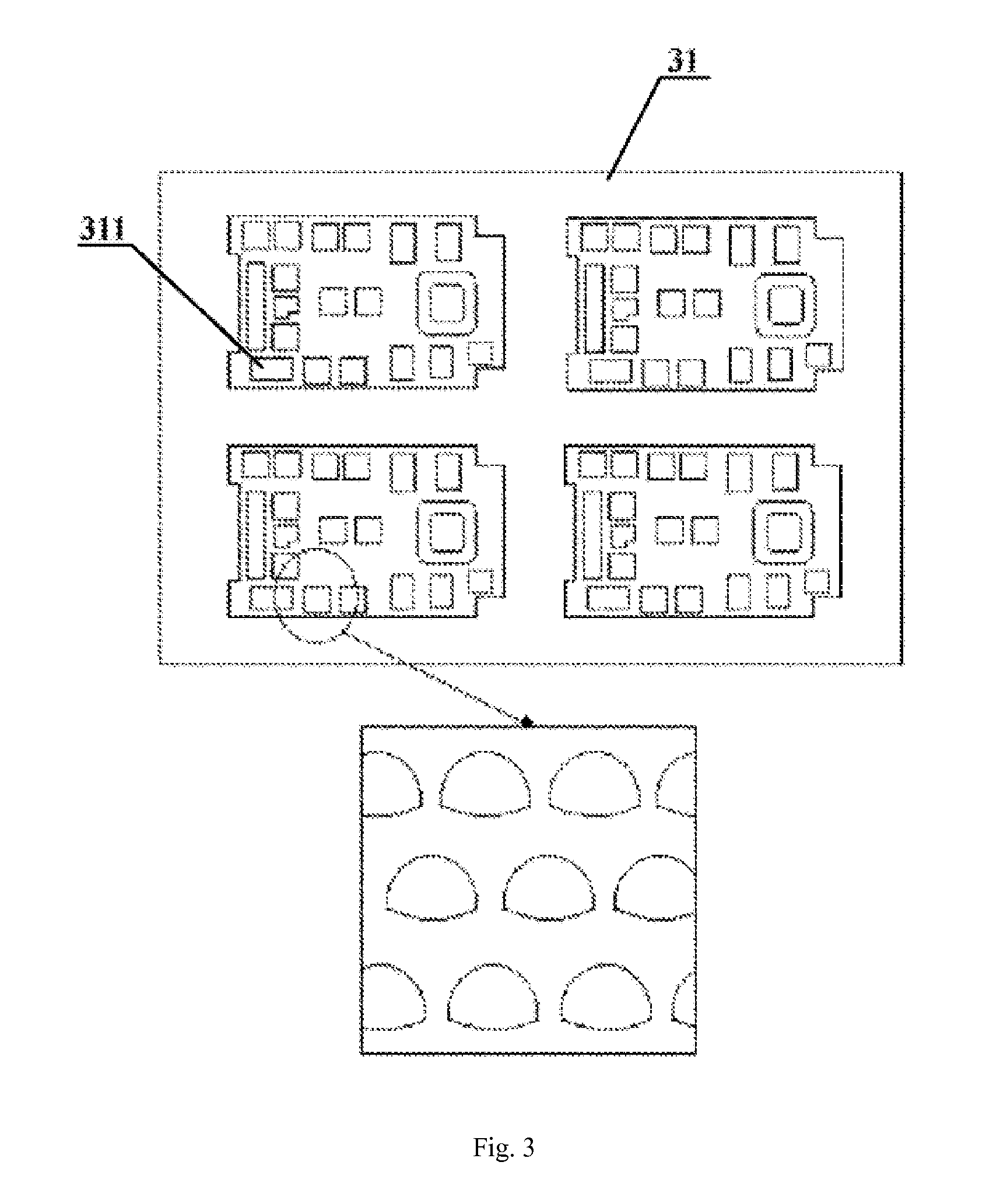
However, diameters of dots formed in ink injecting manner are limited to 20-120 um, and the dots are substantially in microlens shape.

Method used


Image

  • Apparatus for manufacturing light guide film
  • Apparatus for manufacturing light guide film
  • Apparatus for manufacturing light guide film

Examples


first embodiment

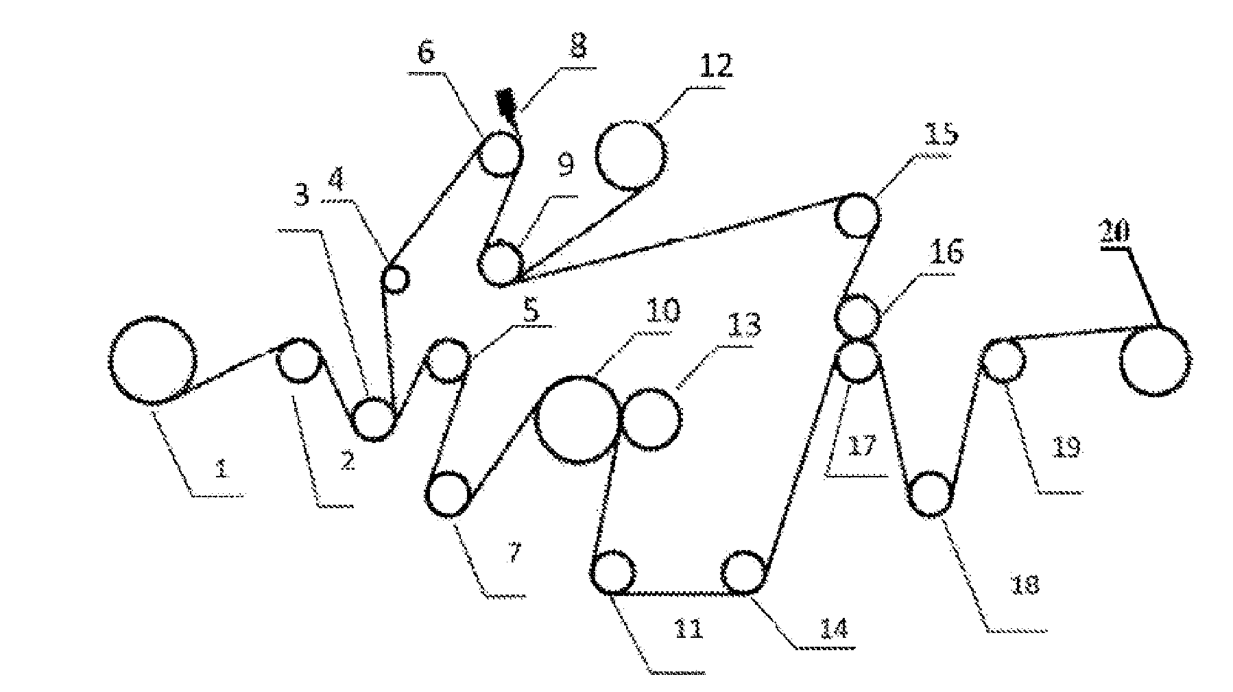
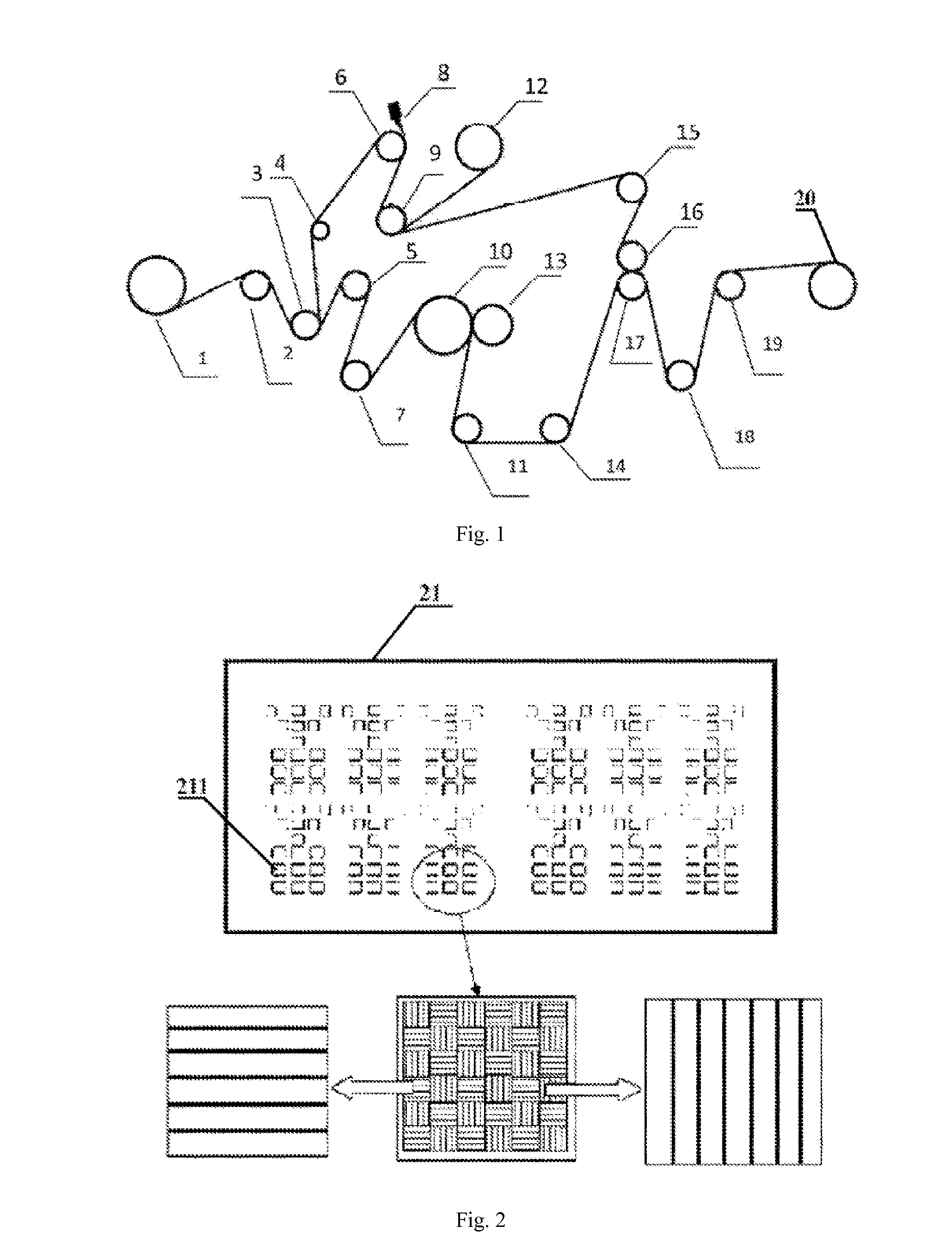
[0028]Referring to FIG. 1, an apparatus for manufacturing a light guide film according to a first embodiment of the present invention is shown. As shown, the apparatus may comprise a feeding roller 1, a receiving roller 20, a separating device, a hot press printing device and a plurality of auxiliary rollers 2, 4, 5, 7, 9, 11, 14, 15 and 18. The raw material of the light guide film is disposed on the feeding roller 1, and it is recycled by the receiving roller 20 after passing through the separating device, the hot press printing device, the recombining device, and the plurality of auxiliary rollers. It should be noted that the number and arrangements of the plurality of the auxiliary rollers may be designed according to practical needs, which are not mandatorily necessary.

[0029]The separating device is disposed behind the feeding roller 1. And the separating device comprises a separating roller 3, a trimming roller 6, a trimmer 8 and a recycling roller or receiving roller 12. The p...

second embodiment

[0037]FIG. 6 is a schematic view of an apparatus for manufacturing a light guide film according to a second embodiment of the present invention. In this embodiment, except the press printing device, other components or devices are the same or similar to those in the first embodiment. Therefore, detailed description related thereto is hereby omitted for clarity purpose.

[0038]In the press printing device, the molding member for processing the light guide film is fixed onto the imprinting roller 13 with fixtures and extended circumferentially around the imprinting roller by 180 degrees, i.e., only half of the imprinting roller 13 is overlapped with the molding member. Therefore, during impressing, two pressing rollers may be needed to perform front and rear press printing respectively. Compared with the impressing effect in the first embodiment, because there is a gap in the pressing roller of the first embodiment, there are periodic interrupts during the impressing of the light guide ...


PUM

PropertyMeasurementUnit
Angleaaaaaaaaaa
Angleaaaaaaaaaa
Temperatureaaaaaaaaaa

Abstract

An apparatus for manufacturing a light guide film may comprise a feed roller, a receiving roller, a separating device, a hot press printing device and a recombining device. Firstly, the separating device may separate a protective layer from a substrate layer of the light guide film. Secondly, a surface of the substrate layer to be manufactured may be impressed with light guide dots by the hot press printing device, and the recombining device recombine the peeled protective layer to the substrate layer. And lastly, the finished light guide film is recycled by the receiving roller. The apparatus may have advantages such as high output and low cost, and it may manufacture a large dimensioned product.

Description

FIELD[0001]The present disclosure relates to an apparatus for manufacturing a light guide film, more particularly to an apparatus for manufacturing a light guide film that use roll-to-roll hot press printing.BACKGROUND ART[0002]Light guide plate is one of key components in a backlight module of a LCD display, mobile phone, digital camera and illumination etc. Currently, the method for manufacturing the light guide plate can be divided into printing and non-printing. In printing, a printing material which is highly astigmatic, such as SiO2 and TiO2 etc., is distributed properly at a bottom surface of the light guide plate. Due to properties of light absorption and light diffusion of the printing material, internal transmission induced by optical total reflection is broken up, and the light is emitted from the front face and distributed evenly at a light emitting area. In non-printing, a molding member having a predetermined pattern is prepared first, and the pattern is formed on the ...

Claims


Application Information

Patent Timeline
IPC IPC(8): B28B11/08
CPCB29C59/04B32B37/203B32B38/06G02B6/0065B32B2590/00G02B6/0036B32B2551/00
Inventor WU, ZHIHUAZHOU, XIACHONGFANG, ZONGBAOSHEN, SUWEI, GUOJUNPU, DONGLINCHEN, LINSEN
Owner SVG TECH GRP CO LTD
Learn More