Control device for internal combustion engine

a control device and internal combustion engine technology, applied in the direction of electrical control, process and machine control, instruments, etc., can solve the problem of difficult to accurately feedback-control the air-fuel ratio to a target value, the detection value of the air-fuel ratio sensor and the actual exhaust air-fuel ratio, and the time required to reduce the pressure is certain, so as to achieve learning

Inactive Publication Date: 2013-02-14
TOYOTA JIDOSHA KK
View PDF18 Cites 21 Cited by
  • Summary
  • Abstract
  • Description
  • Claims
  • Application Information

AI Technical Summary

Benefits of technology

[0027]The present invention is very effective for enabling learning during the intake throttling delay period.

Problems solved by technology

This results in an error between the detected value from the air-fuel ratio sensor and the actual exhaust air-fuel ratio.
Hence, it is difficult o accurately feedback-control the air-fuel ratio to a target value simply by utilizing the detected value from the air-fuel ratio sensor.
However, even if the throttle valve immediately reaches a target opening degree, a certain amount of time is required to reduce the pressure (that is, the intake pressure) in an intake passage extending from the throttle valve to a cylinder.
This naturally delays a timing for starting the learning.
However, the after-injection also cannot be carried out during the intake throttling delay period.
This is because, during the intake throttling delay period, intake pressure fails to lower sufficiently, resulting in a relatively high intra-cylinder pressure and the presence of excessive air in the cylinder.
Hence, with excessive air present in the cylinder, an intra-cylinder temperature is low during the after-injection.
This may lead to a misfire.
This delays the timing to start the learning, thus increasing the time required to switch the air-fuel ratio from the lean value to the rich value.

Method used


Image

  • Control device for internal combustion engine
  • Control device for internal combustion engine
  • Control device for internal combustion engine

Examples


Embodiment Construction

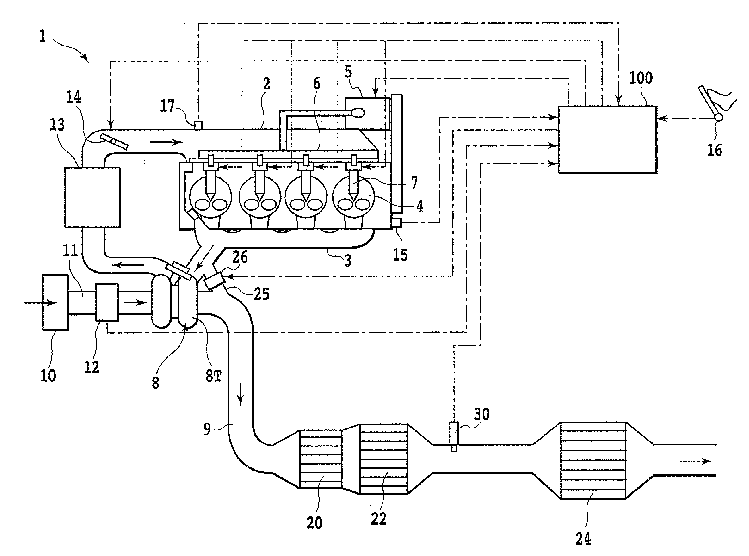
[0044]A preferred embodiment of the present invention will be described based on the accompanying drawings. In the description below, the air-fuel ratio is hereinafter sometimes referred to as the “A / F”. Furthermore, the term “absorption” or “adsorption” may be used synonymously with the term “storage”.

[0045]FIG. 1 schematically shows an internal combustion engine according to the embodiment of the present invention. Reference numeral 1 denotes a compression-ignited internal combustion engine for automobiles, that is, a diesel engine. Reference numeral 2 denotes an intake manifold that is in communication with an intake port. Reference numeral 3 denotes an exhaust manifold that is in communication with an exhaust port. Reference numeral 4 denotes a combustion chamber. The combustion chamber 4 is defined by a cylinder and a piston. The expression “in the cylinder” or “intra-cylinder” is synonymous with the expression “in the combustion chamber” or “intra-combustion chamber”. In the p...


PUM


Abstract

A control device for an internal combustion engine switches an air-fuel ratio of an air-fuel mixture in a cylinder from a first air-fuel ratio leaner than stoichiometry for normal operation to a second air-fuel ratio richer than the stoichiometry. During a switching period from beginning to end of the switching, the control device carries out intake throttling to control the air-fuel ratio of the air-fuel mixture in the cylinder to a third air-fuel ratio richer than the first air-fuel ratio and leaner than the stoichiometry, while learning a correction value for a fuel injection amount. During the switching period, before the intake throttling is completed, the control device carries out such a post-injection as prevents injected fuel from being combusted and learns the correction value. After the intake throttling is completed, the control device carries out such an after-injection as allows the injected fuel to be incompletely combusted and learns the correction value.

Description

TECHNICAL FIELD[0001]The present invention relates to a control device for an internal combustion engine, and in particular, to a control device for an internal combustion engine which is configured to switch the air-fuel ratio of an air-fuel mixture in a cylinder from a lean value to a rich value.BACKGROUND ART[0002]As is known, in internal combustion engines such as diesel engines in which combustion occurs in a lean state (excessive oxygen), an NOx catalyst configured to reduce and purify nitrogen oxide (NOx) is provided in an exhaust passage. Furthermore, storage reduction NOx catalysts are known which are configured to emit NOx for reduction in a rich state (excessive fuel).[0003]In order to allow periodic emission of NOx stored in the storage reduction NOx catalyst and sulfur attaching to the catalyst in connection with sulfur (S) components in the fuel, the air-fuel ratio of the air-fuel mixture is periodically switched from the lean value to the rich value. That is, an air-f...

Claims


Application Information

Patent Timeline
Patent Type & Authority Applications(United States)
IPC IPC(8): F02D41/30
CPCF02D41/025F02D41/0275F02D41/028Y02T10/26F02D41/1475F02D41/405Y02T10/44F02D41/06Y02T10/12Y02T10/40
Inventor NOGI, YOSHITO
Owner TOYOTA JIDOSHA KK
Why Eureka
Try Eureka