Exhaust gas recirculation system for an internal combustion engine

Active Publication Date: 2013-02-21
GM GLOBAL TECH OPERATIONS LLC
View PDF16 Cites 9 Cited by
  • Summary
  • Abstract
  • Description
  • Claims
  • Application Information

AI Technical Summary

Benefits of technology

The invention is a solution for improving the efficiency and reducing the fouling of an EGR system in an internal combustion engine. It allows for better control of the temperature of the coolant used in the second EGR cooler, which leads to faster warming of the coolant and reduces boiling effects. This results in improved engine efficiency and reduced fouling of the second EGR cooler.

Problems solved by technology

In particular conditions, for example during the engine start-up phase in a cold environment, it could happen that the coolant used in the EGR cooler system is excessively cool.
If such excessive cool coolant is supplied to the EGR cooler, the exhaust gas is also excessively cooled, resulting in an excessive decrease in temperature of the intake air.
This may cause misfires in the internal combustion engine, adversely affecting the drivability.
These acids can, over time, cause the corrosion of the components of the EGR system.
In addition, when the temperature of the coolant is excessively low, the soot contained in exhaust gas is prone to settle on the interior surfaces of the EGR, causing the latter to be less efficient and leading to fouling and potential plugging.

Method used


Image

  • Exhaust gas recirculation system for an internal combustion engine
  • Exhaust gas recirculation system for an internal combustion engine
  • Exhaust gas recirculation system for an internal combustion engine

Examples


Embodiment Construction

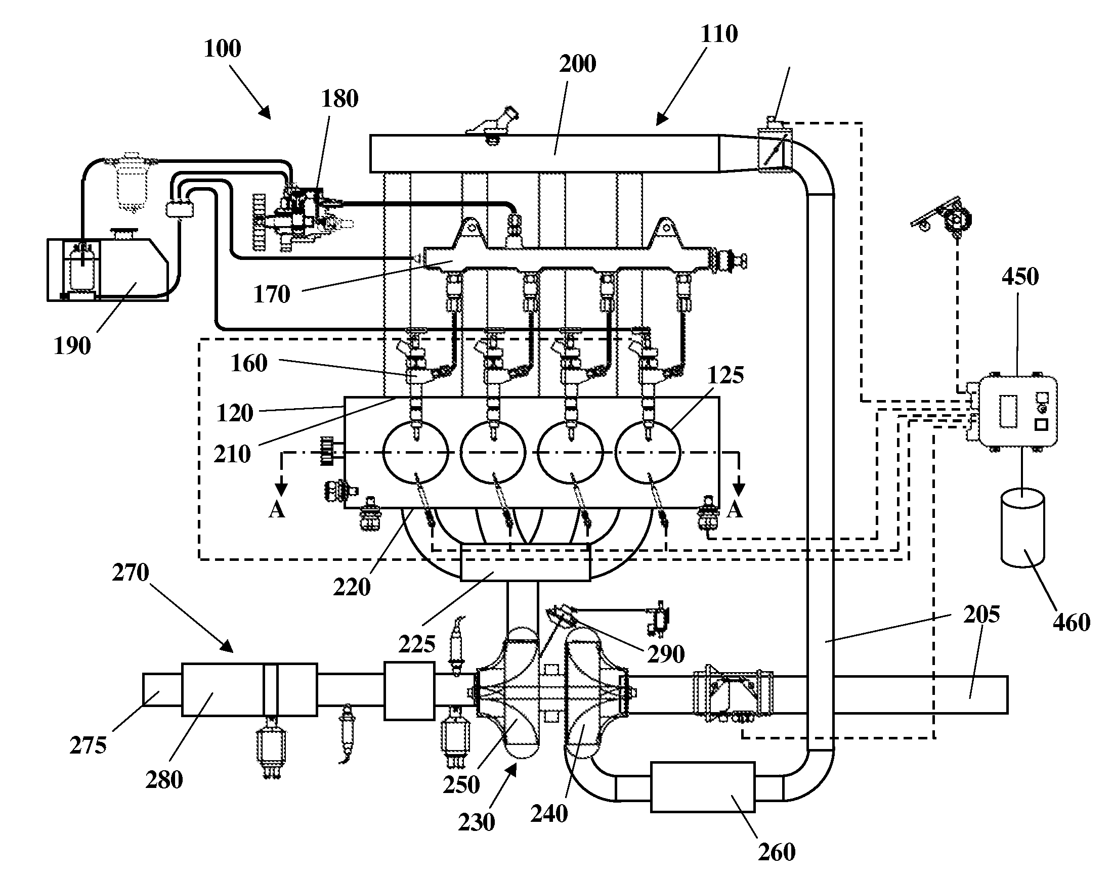
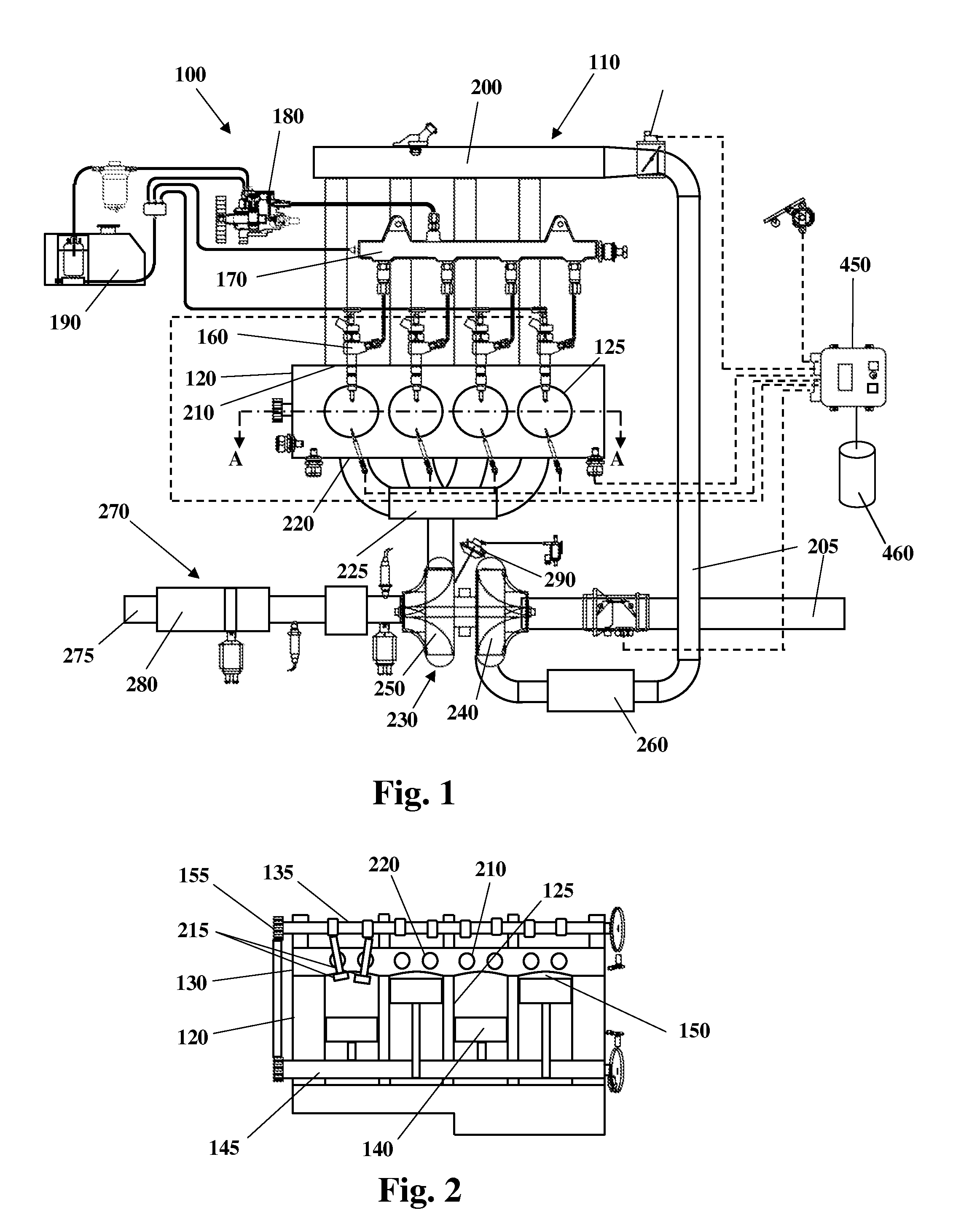
[0035]Some embodiments may include an internal combustion engine system 100, as shown in FIGS. 1 and 2, that includes an internal combustion engine (ICE) 110 having an engine block 120 defining at least one cylinder 125 having a piston 140 coupled to rotate a crankshaft 145. A cylinder head 130 cooperates with the piston 140 to define a combustion chamber 150. A fuel and air mixture (not shown) is disposed in the combustion chamber 150 and ignited, resulting in hot expanding exhaust gasses causing reciprocal movement of the piston 140. The fuel is provided by at least one fuel injector 160 and the air through at least one intake port 210. The fuel is provided at high pressure to the fuel injector 160 from a fuel rail 170 in fluid communication with a high pressure fuel pump 180 that increases the pressure of the fuel received from a fuel source 190. Each of the cylinders 125 has at least two valves 215, actuated by a camshaft 135 rotating in time with the crankshaft 145. The valves ...


PUM


Abstract

An exhaust gas recirculation system for an internal combustion engine comprising an exhaust gas recirculation conduit fluidly connecting an exhaust manifold to an intake manifold of the internal combustion engine, first and second exhaust gas coolers located in series in the exhaust gas recirculation conduit, each of the first and second exhaust gas coolers comprising an inlet and an outlet fluidly connected to a first and a second coolant circuit respectively, wherein the second coolant circuit comprises a radiator having a coolant inlet in fluid communication with the coolant outlet of the second exhaust gas cooler, a pump having a coolant inlet in fluid communication with a coolant outlet of the radiator and a coolant outlet in fluid communication with the coolant inlet of the second exhaust gas cooler, and an additional conduit fluidly connecting the coolant outlet of the exhaust cooler.

Description

TECHNICAL FIELD[0001]The present invention relates to an exhaust gas recirculation system for an internal combustion engine, in particular an internal combustion engine of a motor vehicle.BACKGROUND[0002]In order to reduce the polluting emission, most internal combustion engines, principally Diesel engines, are equipped with an exhaust gas recirculation (EGR) system, for selectively routing back a part of the exhaust gas from the exhaust manifold of the internal combustion engine into the intake manifold of the internal combustion engine. The recirculated exhaust gas is mixed with fresh induction air and is fed into the engine cylinders, thereby reducing the production of oxides of nitrogen (NOx) during the combustion process.[0003]Conventional EGR systems comprise an EGR conduit fluidly connecting the exhaust manifold to the intake manifold, an EGR cooler located in the EGR conduit for cooling the exhaust gas before mixing it with the induction air, and a valve for regulating the f...

Claims


Application Information

Patent Timeline
IPC IPC(8): F02M25/07F02B47/08
CPCF02B29/0406F02M25/0707F02M25/0728F02M25/0731F02M25/0732F01P2060/16F02D13/0219Y02T10/121F01P3/20F01P7/165F02M25/0738F02M26/05F02M26/24F02M26/25F02M26/28F02M26/33F02M26/50F02M26/27Y02T10/12
Inventor VASSALLO, ALBERTODRANGEL, HANS H.
Owner GM GLOBAL TECH OPERATIONS LLC
Why Eureka
Try Eureka