
Solid-state high-pressure mixed hydrogen storage device

A high-pressure mixing and hydrogen storage device technology, which is applied in fixed-capacity gas storage tanks, gas/liquid distribution and storage, container filling methods, etc. Mixed into the heat transfer of thermally conductive fibers to avoid aging, reduce weight, improve hydrogen storage density and dynamic response characteristics

Pending Publication Date: 2016-11-23
SHIJIAZHUANG ENRIC GAS EQUIP +2
View PDF8 Cites 8 Cited by
  • Summary
  • Abstract
  • Description
  • Claims
  • Application Information

AI Technical Summary

Problems solved by technology

In the hydrogen storage device of the prior art, the hydrogen storage powder is directly filled into the hydrogen storage tank, which brings many problems to the cleanliness of the hydrogen during the hydrogen discharge, so that the hydrogen contains the fine powder of the hydrogen storage alloy; However, if a bulk hydrogen storage alloy material is used, due to the "bulk" characteristics of the bulk hydrogen storage material, it is impossible to bury the heat conduction sheet or mix the heat conduction fiber to achieve heat transfer. Therefore, the heating / cooling of the bulk hydrogen storage alloy material problem, the prior art does not propose a solution
In addition, the cylinder body of the hydrogen storage device is connected by two parts. Leakage points are easily formed at the welding or connecting parts, which are relatively weak parts. These weak parts often become safety hazards during storage and transportation.

Method used


Image

  • Solid-state high-pressure mixed hydrogen storage device
  • Solid-state high-pressure mixed hydrogen storage device

Examples


Embodiment Construction

[0019] Typical embodiments embodying the features and advantages of the present invention will be described in detail in the following description. It should be understood that the invention is capable of various changes in different embodiments without departing from the scope of the invention, and that the description and illustrations therein are illustrative in nature and not limiting. this invention.

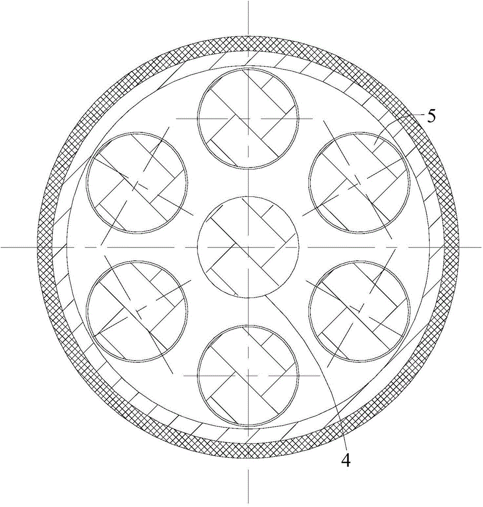
[0020] A specific embodiment of a solid-state high-pressure hybrid hydrogen storage device of the present invention, such as Figure 1-2 As shown, for example, the hydrogen storage device includes a mother tank and seven sub-tanks 4 . Wherein, the mother tank is composed of a mother tank liner 3 and a fiber winding layer 2 outside the steel liner. The inner liner 3 of the mother tank is a seamless steel pipe with both ends necked and spun into one piece. The fiber winding layer 2 can be formed by impregnating carbon fibers, glass fibers, or composite fibers in epoxy resi...


PUM


Abstract

A solid-state high-pressure mixed hydrogen storage device comprises a main tank and multiple sub tanks. An opening in one end of the main tank is a gas inlet / outlet, and an opening in the other end of the main tank is provided with heat exchange pipes. The sub tanks are mounted in the main tank. All the sub tanks are filled with a block-shaped hydrogen storage alloy material. The heat exchange pipes are connected into the corresponding sub tanks and can heat or cool the hydrogen storage material in the corresponding sub tanks. All the sub tanks communicate with an inner cavity of the main tank. Through the sub tanks with the diameter being far smaller than that of the main tank, the radius of heat conducting of each heat exchange pipe to an alloy in the corresponding sub tank is small, the heat exchange pipes can quickly and evenly heat or cool the corresponding block-shaped hydrogen storage alloys, the heat exchange effect is better, and the hydrogen storage performance of the hydrogen storage device better meets the process requirements; and the storage amount of the hydrogen storage alloys of the whole hydrogen storage device is larger due to the sub tanks, and more hydrogen storage alloys are arranged, so that the hydrogen storage efficiency of the hydrogen storage device is higher under the same pressure.

Description

technical field [0001] The invention relates to the technical field of high-pressure tank hydrogen storage devices filled with solid hydrogen storage alloy materials Background technique [0002] Hydrogen energy has become the ultimate solution to the future human energy crisis, and it is also a promising way for human beings to solve the current environmental problems. As a new energy source, hydrogen has unparalleled advantages. However, from hydrogen production to specific applications, hydrogen storage and transportation are an essential part. On November 13, 2006, leading scientists in the field of hydrogen energy submitted the "Centennial Memorandum" on hydrogen energy to the G8, pointing out solutions to the two major crises that human beings are facing at the beginning of the 21st century: climate change and traditional petrochemical energy. Among them, hydrogen energy is the optimal solution, but the problem of hydrogen storage must be overcome. [0003] At prese...

Claims


Application Information

Patent Timeline
Patent Type & Authority Applications(China)
IPC IPC(8): F17C11/00F17C13/00
CPCY02E60/32
Inventor 王兆斌
Owner SHIJIAZHUANG ENRIC GAS EQUIP
Learn More