
System assembly and design of photoelectric controller device

a photoelectric controller and system assembly technology, applied in the direction of optical radiation measurement, electrical apparatus casing/cabinet/drawer, instruments, etc., can solve the problems of interfering with the proper affecting the operation of the photosensor, and being subjected to snow and i

Inactive Publication Date: 2013-02-21
GENERAL ELECTRIC CO
View PDF15 Cites 36 Cited by
  • Summary
  • Abstract
  • Description
  • Claims
  • Application Information

AI Technical Summary

Benefits of technology

The patent text describes a photoelectric controller device that has three printed circuit boards: two parallel with the base plate and one perpendicular to it. The perpendicular board has wireless communication circuitry, which can be embedded in the second board. The device also has a flexible third board, a protective coating on the window, and a thin film of light transmissive material. Additionally, the base plate has cutouts that engage with ramp members, and polymeric resin secures the base plate to the housing. The technical effects of this design include improved wireless communication and protection of the device's components.

Problems solved by technology

It also may be subjected to snow and ice.
The window may become coated with dust, snow and ice, interfering with proper operation of the photosensor.
High pressure water spray, high velocity dust, snow, ice and extended periods of direct sunlight is a problematic environment for a high voltage electronic device to be subjected to.

Method used


Image

  • System assembly and design of photoelectric controller device
  • System assembly and design of photoelectric controller device
  • System assembly and design of photoelectric controller device

Examples


Embodiment Construction

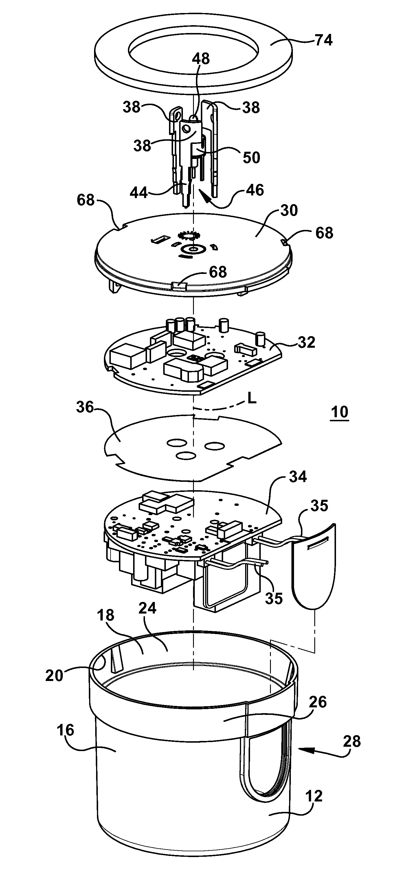
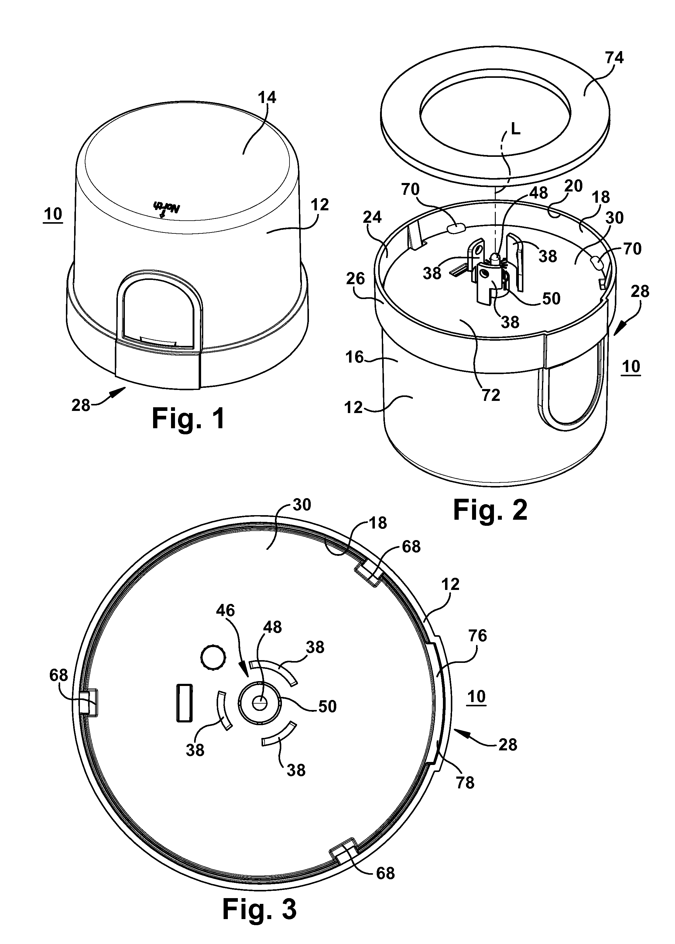
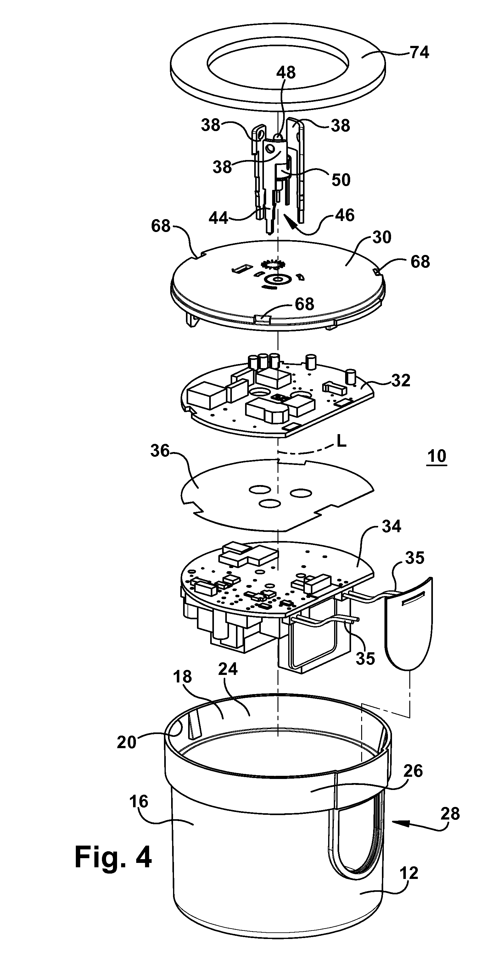
[0035]Referring to FIGS. 1-4 of the drawings, a photoelectric controller device 10 includes a housing or cover 12 in the shape, for example, of a generally cylindrical cup. The housing 12 includes an end (e.g., upper) surface 14 and a side wall 16 extending transverse from the end surface to a lip 18 that extends around an open end 20 of the housing 12 leading to its interior 22. The housing 12 is elongated along a longitudinal axis L and includes an interior surface 24 and exterior surface 26. A window 28 is disposed in the side wall 16 of the housing 12. An electrically insulating base plate 30 is secured to the housing near the open end 20. Outer and inner printed circuit boards (PCBs) 32, 34, which are electrically connected to each other such as by the electrical wires 35 between them, are disposed in the interior 22 of the housing 12 and are connected to the base plate 30. An electrically insulating polymer layer 36 is disposed between the PCBs 32, 34. Three main high voltage ...


PUM


Abstract

A photoelectric controller device includes a housing. At least two printed circuit boards can be secured in an interior of the housing. The printed circuit boards include a photosensor and communication circuitry. Electrically conductive, main terminals are secured in electrical contact with one of the printed circuit boards. A communication terminal is also secured in electrical contact with the communication circuitry on one of the printed circuit boards. Also featured is a design of a base plate of the photoelectric controller device that secures at least one circuit board and a design of a window for the photosensor. The controller may include at least one printed circuit board comprising a sensor selected from the group consisting of the photosensor, an infrared sensor or a visible detector, and combinations thereof.

Description

FIELD OF THE INVENTION[0001]This disclosure pertains to a photoelectric controller device and, in particular, to features enabling the device to resist UV degradation, dust and a high pressure water spray and, to the assembly of a PCB board and connectors.BACKGROUND OF THE INVENTION[0002]Lighting fixtures can be automatically switched on at dusk and off at dawn using twist-lock photoelectric controllers. The lighting fixtures may be used to light roads, parking lots and other areas outdoors. The photoelectric controller senses the intensity of the ambient light and switches the lighting fixtures on and off as appropriate. The photoelectric controllers are typically oriented so that the photosensor faces North, away from direct sunlight in the Northern hemisphere (and in a southerly direction in the Southern hemisphere). It is also desired to be able to easily adjust the receptacle that receives the photoelectric controller to achieve the desired orientation.[0003]Lighting fixtures f...

Claims


Application Information

Patent Timeline
IPC IPC(8): H05K7/00
CPCG01J1/0271G01J1/0403G01J1/0407F21W2131/10F21V23/0442F21V23/0464F21V15/01F21W2131/103
Inventor CREIGHTON, JASONAURONGZEB, DEEDERABOUMRAD, TONYSELECKY, MICHAEL
Owner GENERAL ELECTRIC CO
Learn More