
Dragline rope ferrule

Active Publication Date: 2013-02-28
BEKAERT WIRE ROPES
View PDF5 Cites 8 Cited by
  • Summary
  • Abstract
  • Description
  • Claims
  • Application Information

AI Technical Summary

Benefits of technology

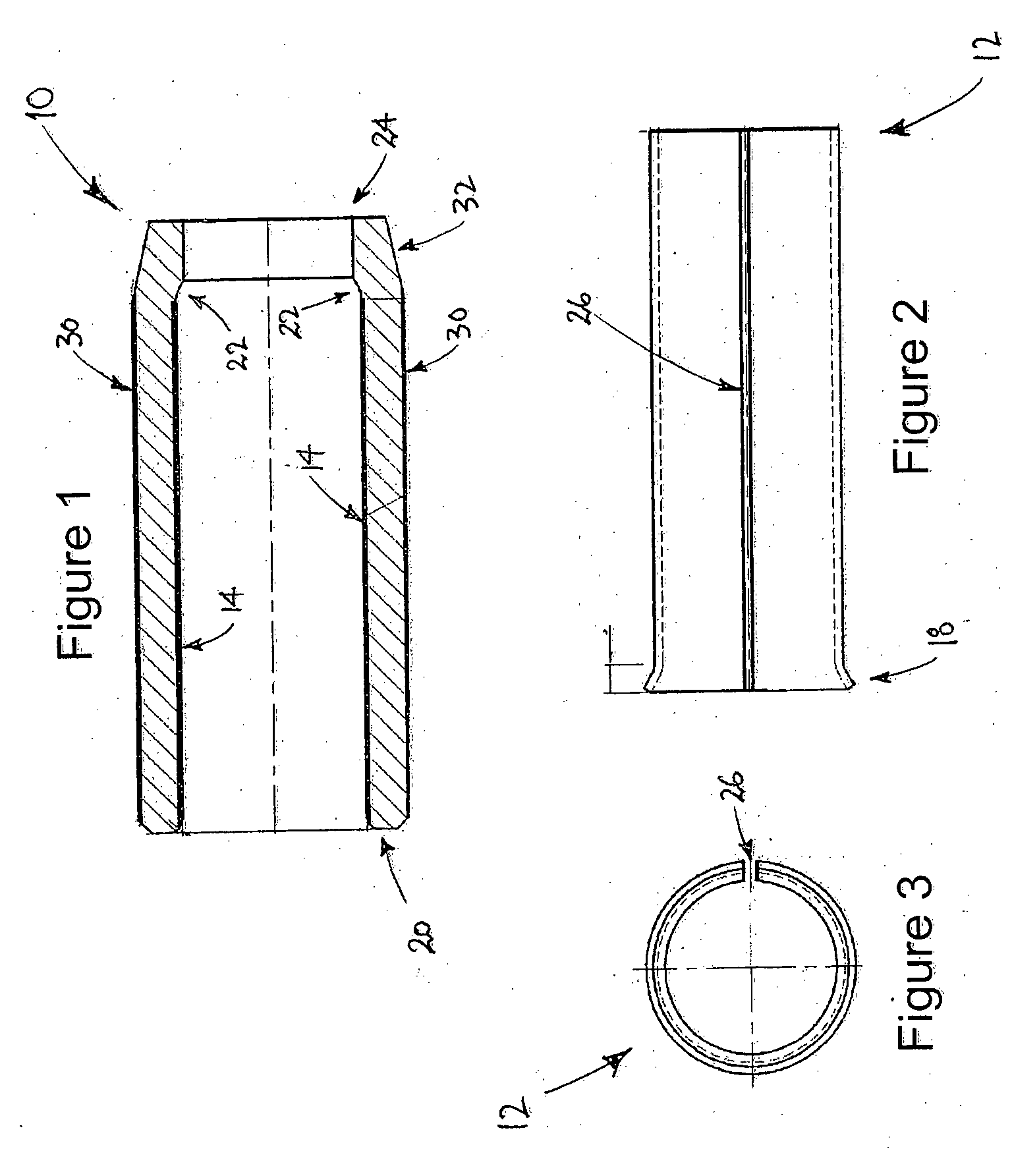
The patent text describes a method for improving the strength of a ferrule in a dragline rope, which helps prevent the ferrule from being pulled off during use. This also makes it easier to change the rope and reduces downtime for maintenance. The method involves adapting the body and lining of the ferrule to prevent the lining from being squeezed out during manufacturing. Overall, this results in a stronger and more durable dragline rope.

Problems solved by technology

Large capacity mining draglines subject a dragline bucket to enormous forces and loads.
The ropes (also referred to as “cables”) are employed in draglines to control the various movements of the bucket, and accordingly experience extreme and rapid wear, especially at the sheaves in components of the dragline.
Rope replacement is time consuming, with “downtime” of the dragline representing a significant cost in mining operations.
However, such methods are unlikely to provide sufficient securement of a ferrule to a wire rope for dragline conditions.
The profiling of the ferrule necessitates a lateral pressing, hence the method of GB 1,369,211 is not concerned with nor able to address the securement requirements of a ferrule to a dragline rope.

Method used


Image

  • Dragline rope ferrule
  • Dragline rope ferrule
  • Dragline rope ferrule

Examples


example 1

Die-Pressing of Ferrule onto a Dragline Rope

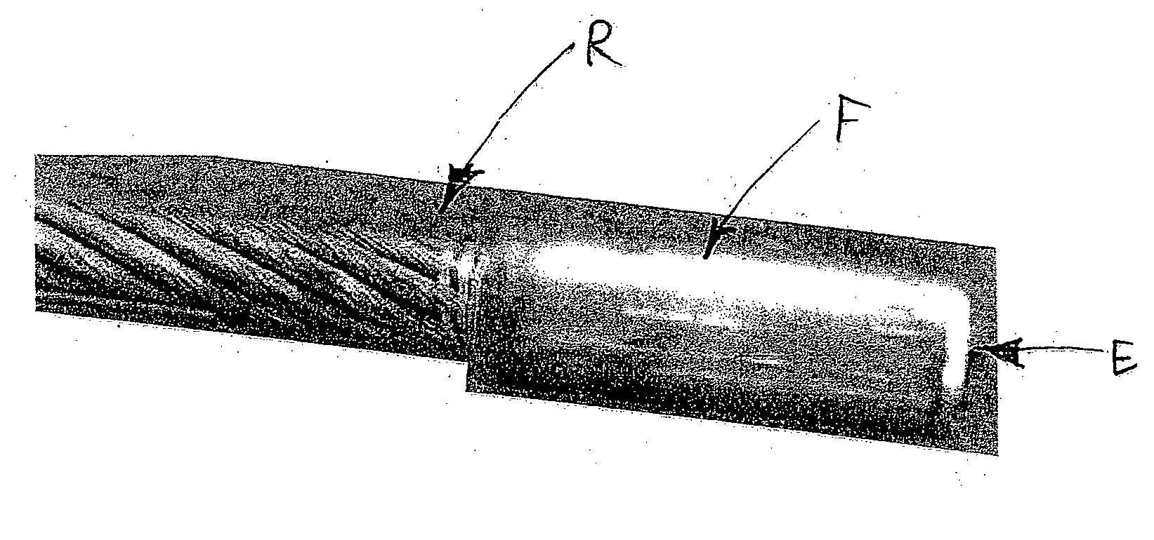
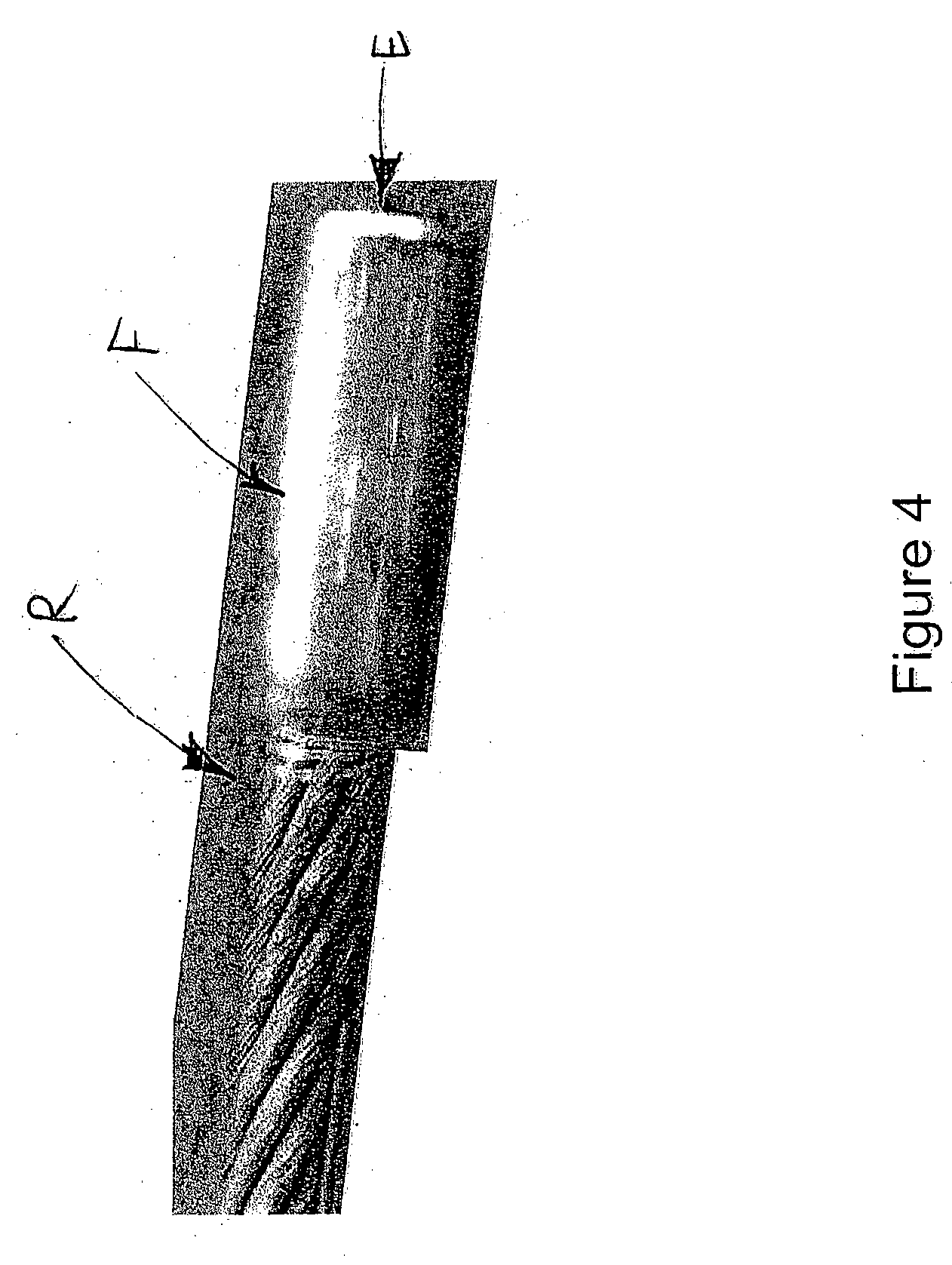
[0064]A ferrule die-pressing procedure was employed, which adopted a methodology whereby an assembly of the ferrule and a dragline rope were pushed through a die with an interference fit. This was observed to effectively extrude the ferrule over the rope, resulting in the ferrule being clamped onto (deformed against) the rope. Referring to FIG. 6, the die-press was set up as follows:[0065]1. A dragline rope end was positioned through the die from the back (parallel) opening Ob, exiting through the front (tapered) opening Ot. The rope R was a multi-stranded wound wire rope of e.g. 6 or 8 wire strands, helically wound around a core or king wire. Each such strand defined a lay length, being the linear length of a rope portion corresponding to a strand having spiralled once around the rope circumference.[0066]2. A ferrule F with its inside lined with the aluminium sleeve S was then slid over the rope end, leaving a calculated length of rope pr...

example 2

Pull-Off Testing of Ferrule on Dragline Rope

[0072]Various dragline rope products resulting from the general procedure of Example 1 were subjected to ferrule pull-off testing, to determine the suitability of the ferrule for use on a dragline rope, as well as optimum ferrule and die press set-ups and configurations. The results of these tests are presented graphically in FIGS. 7 and 8.

[0073]To test the pull-off force (in kN) of a ferrule die-pressed onto a dragline rope product, so as to indicate the strength of the ferrule-to-rope attachment, the following procedure was implemented:[0074]Load the dragline rope into an Avery 3000 kN testing machine.[0075]Seat the ferruled rope end into test blocks, specially designed to transfer load onto the end of the ferrule.[0076]Apply force at a predetermined strain rate.[0077]Continue until ferrule-to-rope bond breaks, and record the load at breakage.

[0078]For each helically wound wire dragline rope, the ferrule had been die-pressed to have a le...


PUM

PropertyMeasurementUnit
Fractionaaaaaaaaaa
Lengthaaaaaaaaaa
Diameteraaaaaaaaaa

Abstract

A method is disclosed for attaching a ferrule to a dragline rope. The method comprises locating the dragline rope in a die of a die-press, locating over the dragline rope a ferrule that is lined internally with a deformable material, and forcing the ferrule longitudinally through the die. The ferrule is caused to be internally expanded and be extruded back over the dragline rope, causing the lining to deform directly against the dragline rope and fastening the ferrule to the dragline rope.

Description

TECHNICAL FIELD[0001]Disclosed is a method for attaching a ferrule to a dragline rope, as well as a dragline rope comprising a ferrule, and a ferrule for the dragline rope. The method finds particular, though not exclusive, application in relation to dragline dump ropes, and will in part be described in this context. However, it is to be appreciated that the method can be employed to attach ferrules to hoist as well as drag ropes in a dragline. The method can also be employed on other steel wire ropes that are used in both mining and civil engineering applications, where a high degree of ferrule-to-rope securement is required.BACKGROUND ART[0002]Large capacity mining draglines subject a dragline bucket to enormous forces and loads. The ropes (also referred to as “cables”) are employed in draglines to control the various movements of the bucket, and accordingly experience extreme and rapid wear, especially at the sheaves in components of the dragline. For example, hoist ropes may nee...

Claims


Application Information

Patent Timeline
IPC IPC(8): F16G11/02D02G3/02B23P11/00
CPCB21D39/04D07B9/00Y10T24/398F16G11/02Y10T29/49826E02F3/54E02F3/48E02F3/58
Inventor MORGAN, ANDREWGREEN, NORMAN
Owner BEKAERT WIRE ROPES
Learn More