Apparatus and method for forming glass sheets

a technology of glass sheets and glass tempering, which is applied in the direction of glass rolling apparatus, glass tempering apparatus, manufacturing tools, etc., can solve the problems of limiting the degree to which a desirably high compressive stress can be created on the surface of glass, affecting the aesthetics of the surface, and difficult to build in the desired stress, etc., to achieve more compressive stress and high compressive stress

Inactive Publication Date: 2013-02-28
CORNING INC
View PDF8 Cites 29 Cited by
  • Summary
  • Abstract
  • Description
  • Claims
  • Application Information

AI Technical Summary

Benefits of technology

[0005]When glass that has been cooled relatively rapidly is placed in an ion-exchange bath at elevated temperature, the atomic structure will relax, the degree of which is dependent upon temperature and time, as well as the composition of the glass and the rate at which the glass was cooled from the melt. In an ion-exchange process for glass sheets, the intent is to build compressive stress into the sheet surface. If the ion exchange process is performed at a high temperature, the glass structure relaxes in the ion-exchange bath and it will therefore be difficult to build-in the desired stress because the stress is being relieved. This structural relaxation limits the degree to which a desirably high compressive stress can be created in the surface of the glass, since the relaxation is constantly competing against the process intended to build-up compressive stress at the surface. Stuffing larger ions, such as potassium ions, into smaller ionic sites, such as sodium sites (during ion-exchange) in a pre-relaxed, denser structure allows the glass to build-in more compressive stress at the surface.
[0007]Disclosed herein is a process that enhances the value of a glass sheet by reducing the degree of compaction, structural relaxation, or dimensional change incurred by the glass sheet in subsequent thermal processing of the sheet and / or product (e.g. when coatings are applied to the glass, the glass is thermally bonded to another material, or when the glass sheet / product is chemically strengthened). One application of the process is directed to discrete sheets that have been cooled relatively rapidly through the transformation temperature range of the glass. However, the process may be applied in a continuous fashion to an extended ribbon (i.e. more than several meters in length) of glass delivered from a down draw process, or the like. In the latter case, segmentation of the ribbon into discrete sheets occurs upon completion of the extended heat treatment process. The process, in its broadest terms, involves controlled cooling of glass sheets that have been formed to near-net shape (thickness, length and width) or a ribbon that has been formed to a desired thickness and width prior to being delivered to a molten metal bath having a temperature range that enables the glass sheet to be pre-compacted, or otherwise heated to an extent where the fictive temperature of the glass is substantially reduced. Such an approach is particularly well suited to a down draw process such as the fusion down draw process.
[0009]The method disclosed herein allows the glass ribbon, or in some instances an individual glass sheet, to be floated in a horizontal orientation on a denser, molten metallic liquid that maintains the ribbon, or the individual glass sheet, in a flat and otherwise undistorted shape. Moreover, when the glass ribbon or sheet is floated and its structure or fictive temperature is appropriately adjusted, it is not subject to the degree of distortion that may be incurred by, for example, hanging the sheets in a furnace or lehr, or supporting the sheets in a fixture or container, after they have been segmented from the ribbon. Likewise, the surface of the ribbon or sheet is not substantially marred by contacting a hard support material (e.g. setter tile) if the ribbon or sheet was thermally processed in a horizontal orientation. The process described herein is particularly well-suited to glass that is relatively thin, e.g. equal to or less than 2 mm in thickness, equal to or less than 1 mm in thickness, or even equal to or less than 0.7 mm in thickness. The advantage of thin ribbon or sheet is that it becomes increasingly more flexible as the thickness decreases. A thinner ribbon of glass may be turned from a vertical orientation using a catenary device that conveys the ribbon through a predetermined arc from a vertical to a horizontal orientation. Such a catenary device should hold and / or convey the ribbon at the extremes of its width, e.g. in the bead area of fusion-drawn glass. Alternatively, the ribbon may be turned in the course of an arc using an air bearing to the forward or leading edge of a molten metal bath. In both cases, the so-called quality area of the ribbon or sheet is untouched by mechanical devices as it is conveyed from a vertical to a horizontal orientation. As used herein, the term “quality area” refers to the portion of the glass sheet or ribbon that is eventually incorporated into a final device. In many processes edge portions of the ribbon or sheet that are contacted, termed non-quality areas, are later removed, either because the contact brings with it potential for damage, or because the non-quality areas may suffer from unacceptable dimensional attributes. In any event, the glass ribbon remains in an enclosure from the vertical position through the horizontal position, thereby eliminating particulate generated while segmenting the ribbon, or in the ambient air, from traveling upward and adhering to the glass because of a chimney effect.

Problems solved by technology

If the ion exchange process is performed at a high temperature, the glass structure relaxes in the ion-exchange bath and it will therefore be difficult to build-in the desired stress because the stress is being relieved.
This structural relaxation limits the degree to which a desirably high compressive stress can be created in the surface of the glass, since the relaxation is constantly competing against the process intended to build-up compressive stress at the surface.
While the pre-relaxation or compaction of the glass may be conducted in common box-type furnaces, or annealing lehrs, the glass is subject to distortion due to gravitational forces and contact with hard refractory materials that can damage the aesthetics of the surface or create strength-limiting flaws.
Down draw processes are generally hampered by the comparatively short distance between where the ribbon is formed at the top of the draw, and the bottom of the draw where the glass has solidified and is cut into the desired shape.
That is, there are practical limits to the physical height of the draw and the length of the glass ribbon.
The higher the draw and therefore the longer the time during which the glass ribbon is suspended, the more difficult it becomes to maintain a stable forming process, particularly when one considers that the glass produced for display-type applications is typically 2 mm or less in thickness, and more typically less than 1 mm in thickness.
Thus, the glass ribbon transits the entire draw height in a matter of minutes, affording very little time to treat the glass in a conventional annealing cycle that might last for tens of minutes or even hours.

Method used


Image

  • Apparatus and method for forming glass sheets
  • Apparatus and method for forming glass sheets
  • Apparatus and method for forming glass sheets

Examples


Embodiment Construction

[0020]In the following detailed description, for purposes of explanation and not limitation, example embodiments disclosing specific details are set forth to provide a thorough understanding of the present invention. However, it will be apparent to one having ordinary skill in the art, having had the benefit of the present disclosure, that the present invention may be practiced in other embodiments that depart from the specific details disclosed herein. Moreover, descriptions of well-known devices, methods and materials may be omitted so as not to obscure the description of the present invention. Finally, wherever applicable, like reference numerals refer to like elements.

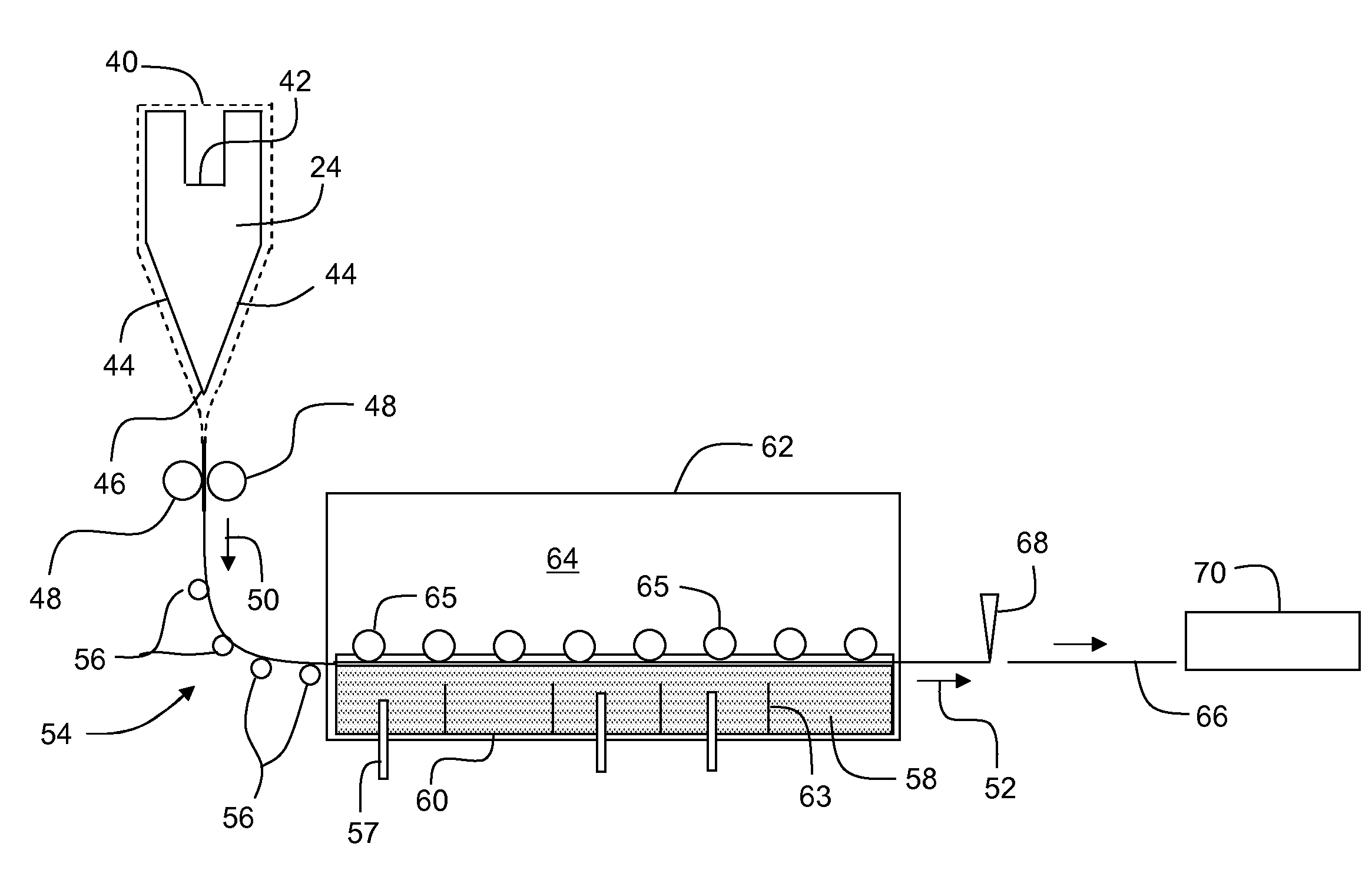
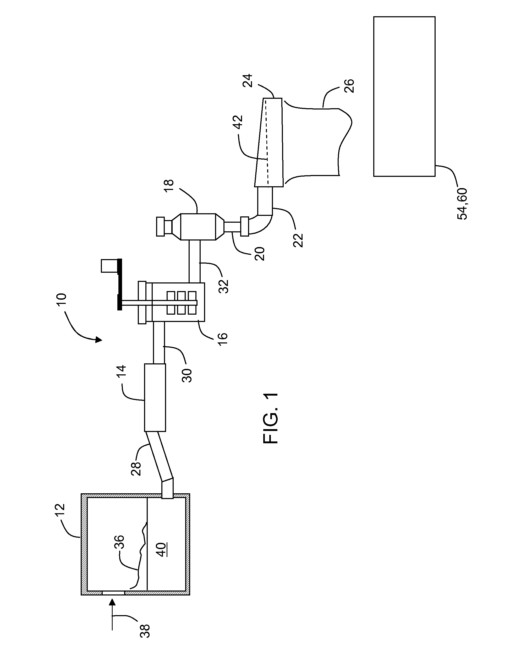
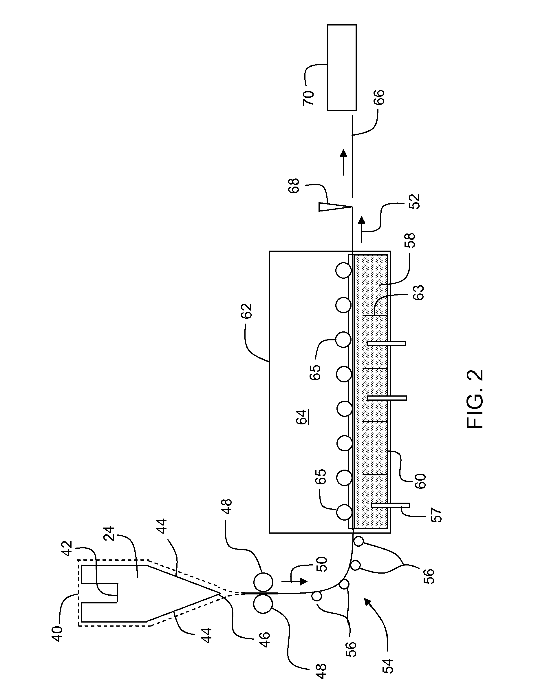
[0021]FIG. 1 illustrates an exemplary embodiment of a fusion glass making system 10 for forming a glass sheet comprising melting furnace 12, fining vessel 14, stirring vessel 16, receiving vessel 18, downcomer 20, inlet 22 and forming body 24 from which a thin ribbon 26 of a molten glass-forming material descends. ...


PUM

PropertyMeasurementUnit
viscosityaaaaaaaaaa
viscosityaaaaaaaaaa
viscosityaaaaaaaaaa

Abstract

Disclosed is a method of reducing the compaction of glass formed by a down draw process. The glass may be a glass sheet or a glass ribbon. Once the glass is formed, it is thermally treated on a molten metal bath for a time and at a temperature effective to reduce the fictive temperature of the glass below a predetermined level. In one embodiment, a glass ribbon is formed in a fusion process and the glass ribbon redirected onto a molten metal bath where the ribbon is thermally treated.

Description

BACKGROUND[0001]1. Field[0002]The present invention relates to the thermal treatment of glass manufactured using a process such as the fusion draw process, or other processes which typically yield discrete sheets from a viscous ribbon of a glass-forming melt.[0003]2. Technical Background[0004]Processes like the fusion-draw process yield sheets of glass that have been cooled relatively rapidly during the forming process and specifically past the annealing point and through the glass transformation temperature range. The benefit of rapid cooling is process throughput and / or the ability to limit the footprint or height of the manufacturing process. However, a relatively rapid cooling process yields a glass that has a relatively open atomic structure, or high molar volume, compared to a glass-forming ribbon that is cooled slowly through the glass transformation temperature range. Moreover, for processes like fusion draw that have a fixed melting and / or flow rate, the formation of thinne...

Claims


Application Information

Patent Timeline
Patent Type & Authority Applications(United States)
IPC IPC(8): C03B17/06C03B33/02C03B32/00C03B25/00C03B18/02C03C21/00
CPCC03B17/061C03B17/064C03B32/00C03B29/025C03B25/093
Inventor KOHLI, JEFFREY T.
Owner CORNING INC
Why Eureka
Try Eureka