Ultrasonic Flow Meter

Active Publication Date: 2013-02-28
APATOR MIITORS APS
View PDF3 Cites 16 Cited by
  • Summary
  • Abstract
  • Description
  • Claims
  • Application Information

AI Technical Summary

Benefits of technology

[0083]Thus, the invention relates especially to high accuracy, high volume, low power and low cost consumption meters for billing purposes.
[0084]By coupling the switching unit, and thereby the transducers, to the output terminal of an operational amplifier of the signal generator and to the inverting input terminal of the operational ampl

Problems solved by technology

One problem to be faced when working with this type of flow meters is that the transducer parameters are not only very likely to differ between samples but also change over time and when the temperature changes.
Such differences and changes alter the shape of the received signal, making it difficult to use this shape as basis for the calculation of the absolute transit time.
Typical acoustical noise sources in an ultrasonic flow meter are edges in the flow current and external vibra

Method used


Image

  • Ultrasonic Flow Meter
  • Ultrasonic Flow Meter
  • Ultrasonic Flow Meter

Examples


Example

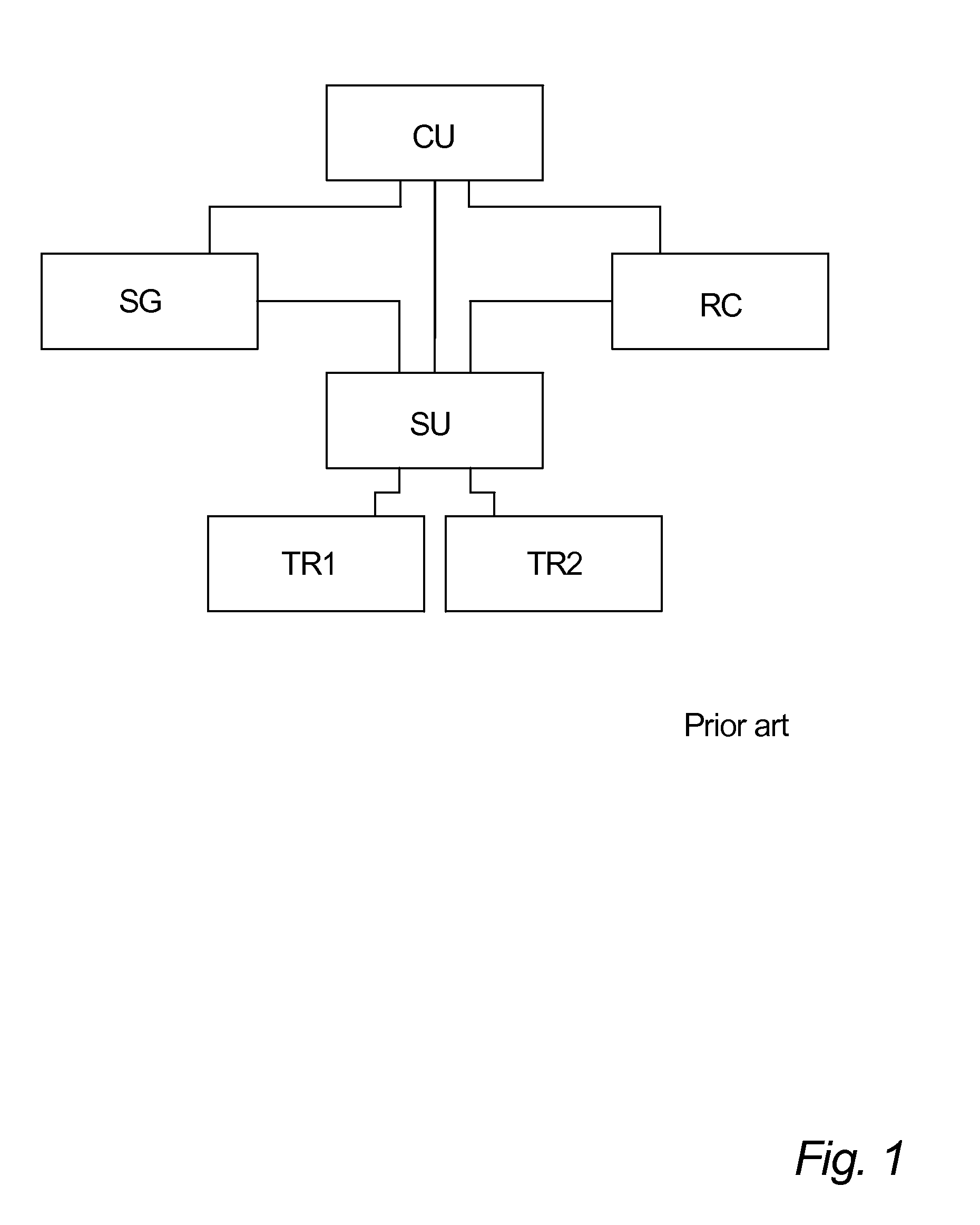
[0143]FIG. 1 shows the overall structure of an ultrasonic flow meter for transit time flow metering as known in the art. A controller unit CU controls the operation of a signal generator SG, a switching unit SU and a receiver circuit RC, where the switching unit SU sets up different electrical connections between the signal generator SG and the receiver circuit RC on one side and two ultrasonic transducers TR1, TR2 on the other side. The two transducers TR1, TR2 are arranged in a flow path FP, in which a fluid flow is to be metered, one transducer TR1 upstream of the other transducer TR2 along the flow path FP.

[0144]In principle, the flow metering is performed in three steps:[0145]1. The switching unit SU is set up to connect the signal generator SG to the first transducer TR1 and to connect the second transducer TR2 to the receiver circuit RC.[0146]An electrical transmission signal, typically a pulsating signal of a frequency of a few megahertz and duration of a few microseconds, i...


PUM


Abstract

An ultrasonic flow meter is disclosed, including a switching unit for switching electrical transmission signals between a signal generator and at least two ultrasonic transducers and for switching electrical reception signal between the transducers and a receiver circuit, wherein the switching unit is coupled to an output terminal of an operational amplifier of the signal generator and to an inverting input terminal of an operational amplifier of the receiver circuit. Furthermore, a method for characterizing an ultrasonic transducer is disclosed, including the step of determining directly from one or more supply current signals for an active component of a signal generator one or more quantities useful for characterizing the transducer. Furthermore, a method for determining the time delay of an ultrasonic signal in a flow path of an ultrasonic flow meter is disclosed, including the step of comparing physically transmitted, delayed and received signals with simulated non-delayed signals.

Description

FIELD OF THE INVENTION[0001]The present invention relates to an ultrasonic flow meter for measuring the flow of a fluid, in particular within the field of transit time flow metering.BACKGROUND OF THE INVENTION[0002]Generally speaking, flow metering by means of the transit time method includes placing two ultrasonic transducers with a suitable mutual distance in the flow path in which the flow of a fluid is to be measured. An ultrasound signal, typically of a frequency of a few megahertz and a duration of a few microseconds, is transmitted through the fluid from the first transducer to the second transducer, and a first transmit time is recorded. Next, a similar ultrasound signal is transmitted through the fluid in the opposite direction, i.e. from the second transducer to the first transducer, and a second transmit time is recorded. Knowing the physical distance between the two transducers, the difference between the two recorded transmit times can be used for calculating the flow r...

Claims


Application Information

Patent Timeline
IPC IPC(8): G01F25/00
CPCG01F1/662G01F25/0007G01F1/667G01F1/668G01F25/10
Inventor DRACHMANN, JENS
Owner APATOR MIITORS APS
Why Eureka
Try Eureka