Water electrolysis system and method for operating the same

Active Publication Date: 2013-02-28
HONDA MOTOR CO LTD
View PDF3 Cites 15 Cited by
  • Summary
  • Abstract
  • Description
  • Claims
  • Application Information

AI Technical Summary

Benefits of technology

[0013]A general object of the present invention is to provide a water electrolysis system capable of minimizing energy consumption for hydrogen dehumidification, and which exhibits improved economic efficiency, convenience, and operational efficiency.
[0014]Anoth

Problems solved by technology

However, since the recovery process contains the heating and cooling steps, the above dehumidification mechanism requires a long recovery time due to the temperature change.
Furthermore, i

Method used


Image

  • Water electrolysis system and method for operating the same
  • Water electrolysis system and method for operating the same
  • Water electrolysis system and method for operating the same

Examples


first embodiment

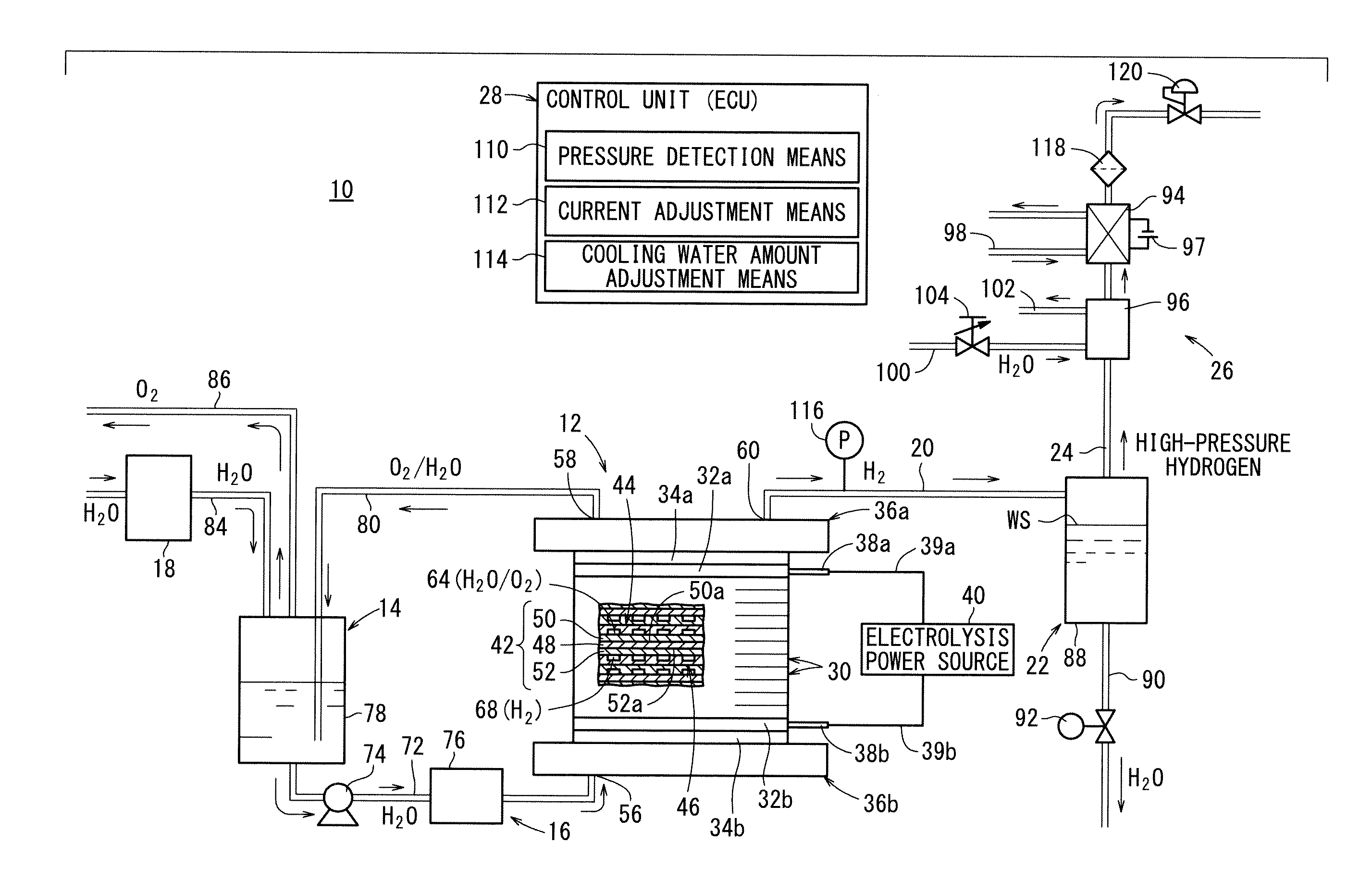
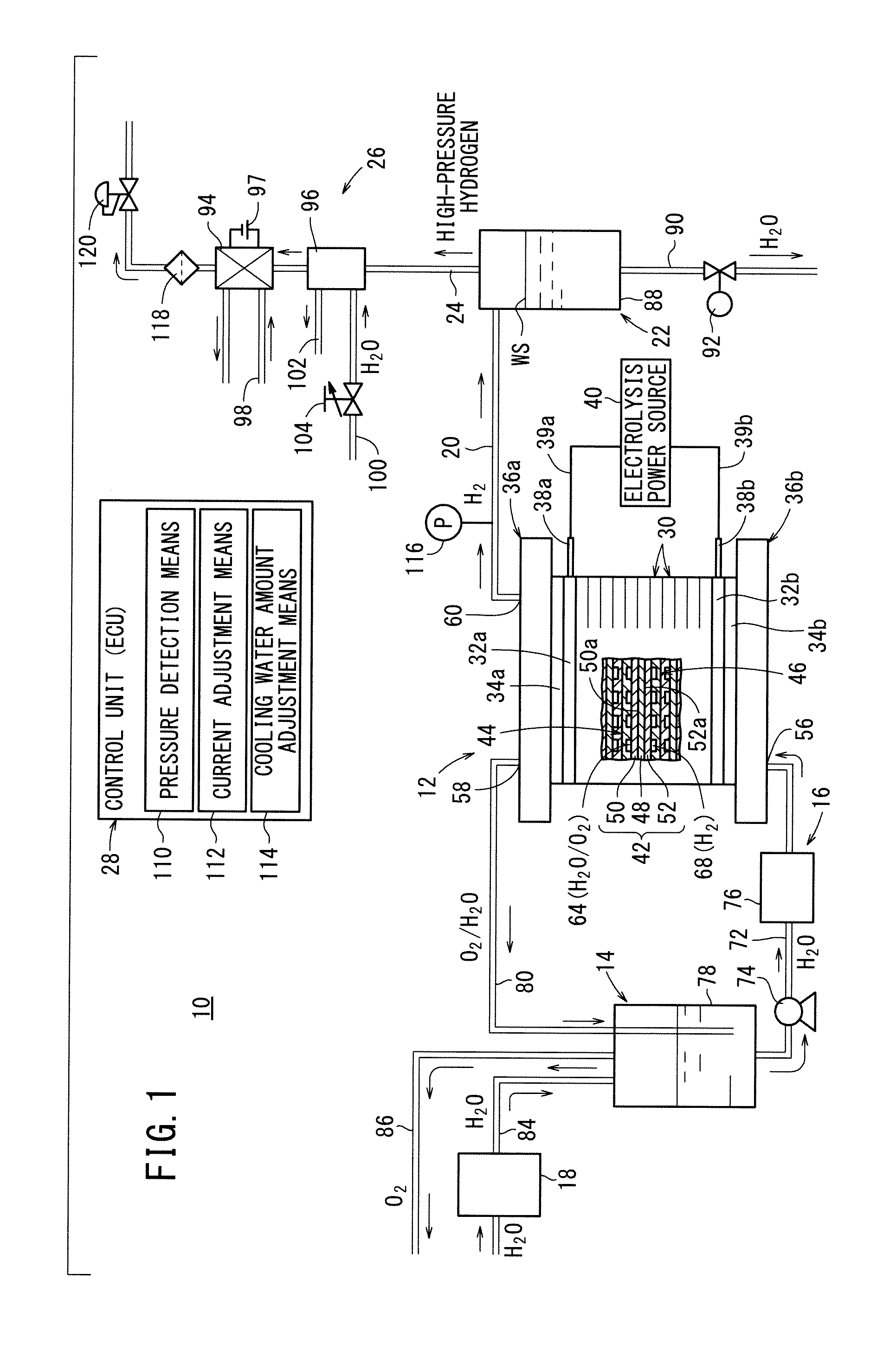
[0045]As shown in FIG. 1, a water electrolysis system 10 according to the present invention includes a high-pressure hydrogen production unit (differential pressure-type water electrolysis apparatus) 12 for electrolyzing water (pure water), thereby producing oxygen (at ordinary pressure) and high-pressure hydrogen (at a pressure higher than the oxygen pressure, e.g., 1 to 70 MPa). The water electrolysis system 10 further includes a water storage unit 14 for separating oxygen and residual water that is discharged from the high-pressure hydrogen production unit 12, and storing the water, a water circulation unit 16 for circulating the water stored in the water storage unit 14 through the high-pressure hydrogen production unit 12, and a water supply unit 18 for supplying pure water prepared from city water to the water storage unit 14.

[0046]The water electrolysis system 10 further includes a gas-liquid separation unit 22 for removing water contained in high-pressure hydrogen, which is ...

third embodiment

[0094]A water electrolysis system 150 according to the present invention is shown in FIG. 9.

[0095]The water electrolysis system 150 has a cooling unit 152 and a control unit 154, which correspond to the cooling unit 26 and the control unit 28 of the first embodiment. Similar to the first embodiment, the cooling unit 152 contains the Peltier dehumidifier 94, and the control unit 154 contains the pressure detection means 110 and the current adjustment means 112, however, the water electrolysis system 150 does not have the heat exchanger 96 or the cooling water amount adjustment means 114.

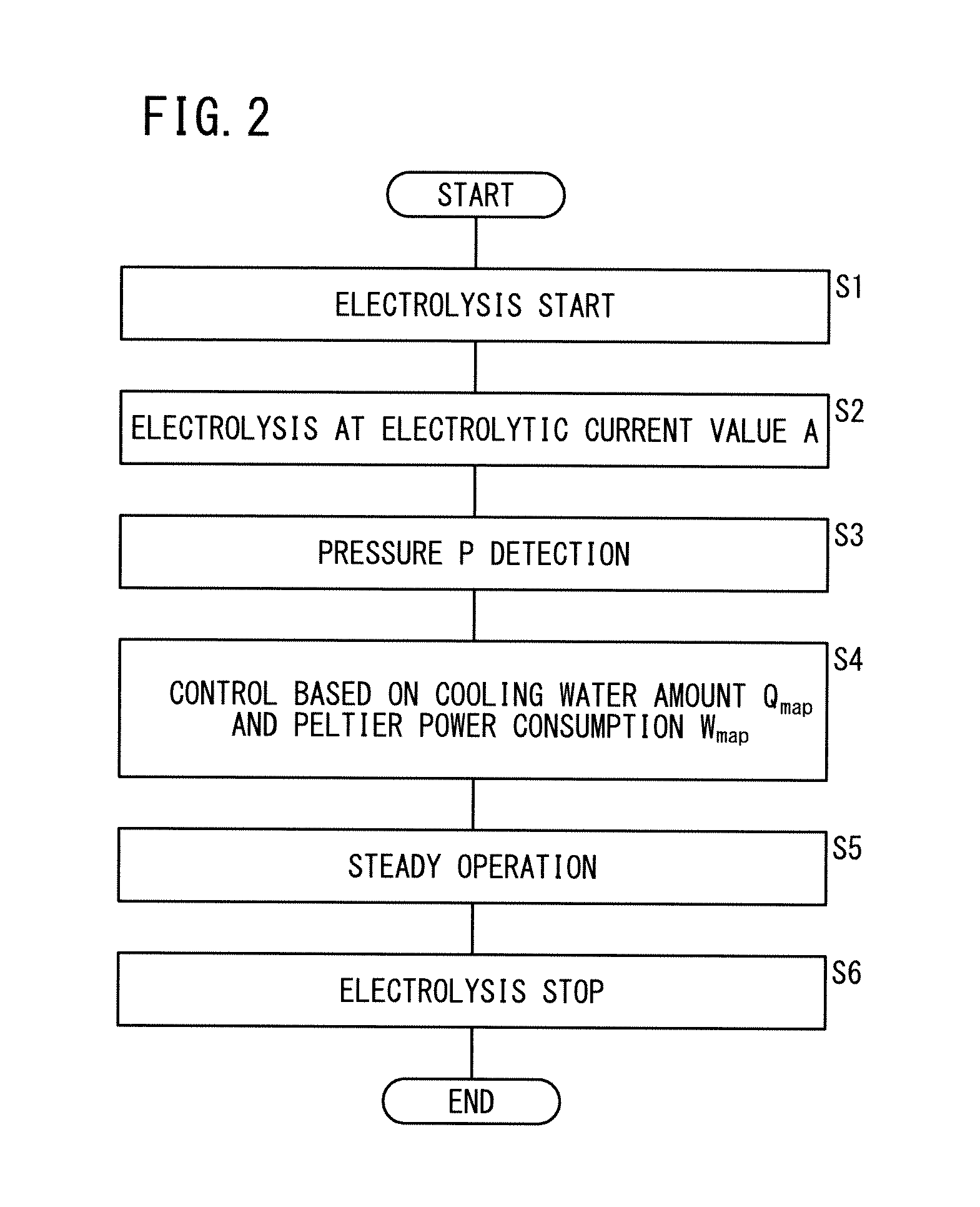
[0096]The water electrolysis system 150 is operated in accordance with the flowchart of FIG. 10, which contains steps S21 to S26. Steps S21 to S23, S25, and S26 are the same as steps S1 to S3, S5, and S6 of the first embodiment (see FIG. 2), respectively, and detailed explanations of such steps are omitted in the third embodiment.

[0097]After steps S21 and S22, in step S23, the pressure P is detected b...

fourth embodiment

[0099]A water electrolysis system 160 according to the present invention is shown in FIG. 11.

[0100]The water electrolysis system 160 has a cooling unit 162 and a control unit 164, which correspond to the cooling unit 26 and the control unit 28 of the first embodiment. The cooling unit 162 contains the heat exchanger 96. The control unit 164 contains the pressure detection means 110 and the cooling water amount adjustment means 114. The water electrolysis system 160 does not have the Peltier dehumidifier 94 or the current adjustment means 112.

[0101]The water electrolysis system 160 is operated in accordance with the flowchart of FIG. 12, which contains steps S31 to S36. Steps S31 to S33, S35, and S36 are the same as steps S1 to S3, S5, and S6 of the first embodiment (see FIG. 2), respectively, and detailed explanations of such steps are omitted in the fourth embodiment.

[0102]After steps S31 and S32, the pressure P is detected by the pressure detection means 110 in step S33. Based on ...


PUM

PropertyMeasurementUnit
Pressureaaaaaaaaaa
Concentrationaaaaaaaaaa
Currentaaaaaaaaaa

Abstract

A water electrolysis system includes a high-pressure hydrogen production unit for electrolyzing water to generate oxygen and high-pressure hydrogen (the pressure of the high-pressure hydrogen being higher than that of the oxygen), and a gas-liquid separation unit for removing water contained in the high-pressure hydrogen. The gas-liquid separation unit is placed on a hydrogen pipe for discharging the high-pressure hydrogen from the high-pressure hydrogen production unit. In addition, the water electrolysis system includes a high-pressure hydrogen supply pipe for transferring dewatered high-pressure hydrogen from the gas-liquid separation unit, a cooling unit, which is placed on the high-pressure hydrogen supply pipe and is capable of variably controlling the temperature of the high-pressure hydrogen to adjust the humidity of the high-pressure hydrogen, and a control unit.

Description

CROSS-REFERENCE TO RELATED APPLICATION[0001]This application is based upon and claims the benefit of priority from Japanese Patent Applications No. 2011-188814 filed on Aug. 31, 2011, and No. 2012-027051 filed on Feb. 10, 2012, of which the contents are incorporated herein by reference.BACKGROUND OF THE INVENTION[0002]1. Field of the Invention[0003]The present invention relates to a water electrolysis system, which has a high-pressure hydrogen production unit for electrolyzing water to generate oxygen at an anode side and hydrogen at a cathode side, and a hydrogen supply pipe for supplying hydrogen generated in the production unit. The present invention also relates to a method for operating such a system.[0004]2. Description of the Related Art[0005]In fuel cells, hydrogen generally is used as a fuel gas for performing a power generation reaction. For example, a water electrolysis apparatus is used to produce hydrogen. The water electrolysis apparatus contains a solid polymer electr...

Claims


Application Information

Patent Timeline
IPC IPC(8): C25B1/12C25B9/04C25B9/00
CPCC25B15/08C25B15/02Y02E60/366C25B1/12C25B1/04C25B9/05Y02E60/36
Inventor KURASHINA, DAISUKENAKAZAWA, KOJINAGAOKA, HISASHIISHIKAWA, HIROYUKIYAMAKAWA, YUJITAKEUCHI, JUN
Owner HONDA MOTOR CO LTD
Why Eureka
Try Eureka