Pitch control of contra-rotating airfoil blades

Active Publication Date: 2013-02-28
GE AVIATION SYST LTD
View PDF6 Cites 16 Cited by
  • Summary
  • Abstract
  • Description
  • Claims
  • Application Information

AI Technical Summary

Benefits of technology

[0006]According to an embodiment of the present invention, a pitch control mechanism for an open rotor gas turbine engine is provided. The engine includes a first rotor assembly and a second rotor assembly, a plurality of airfoil blades circumferentially mounted on each rotor assembly and arranged in contra-rotational relationship to each other. The pitch control mechanism comprises an actuator assembly configured to be secured to a non-rotating frame of the engine,

Problems solved by technology

The use of contra-rotating rotor assemblies provides technical challenges in transmitting power from the

Method used


Image

  • Pitch control of contra-rotating airfoil blades
  • Pitch control of contra-rotating airfoil blades
  • Pitch control of contra-rotating airfoil blades

Examples


Embodiment Construction

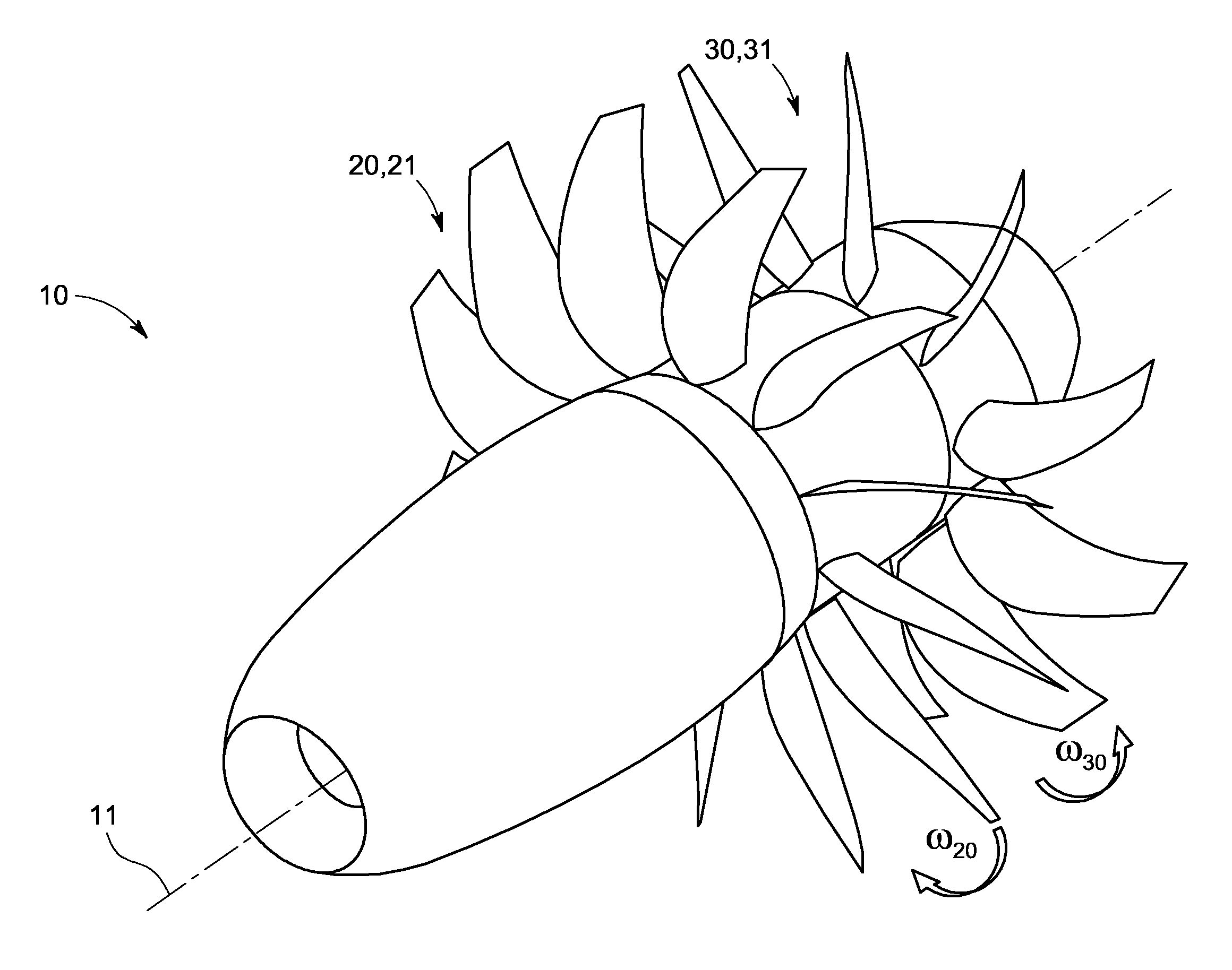
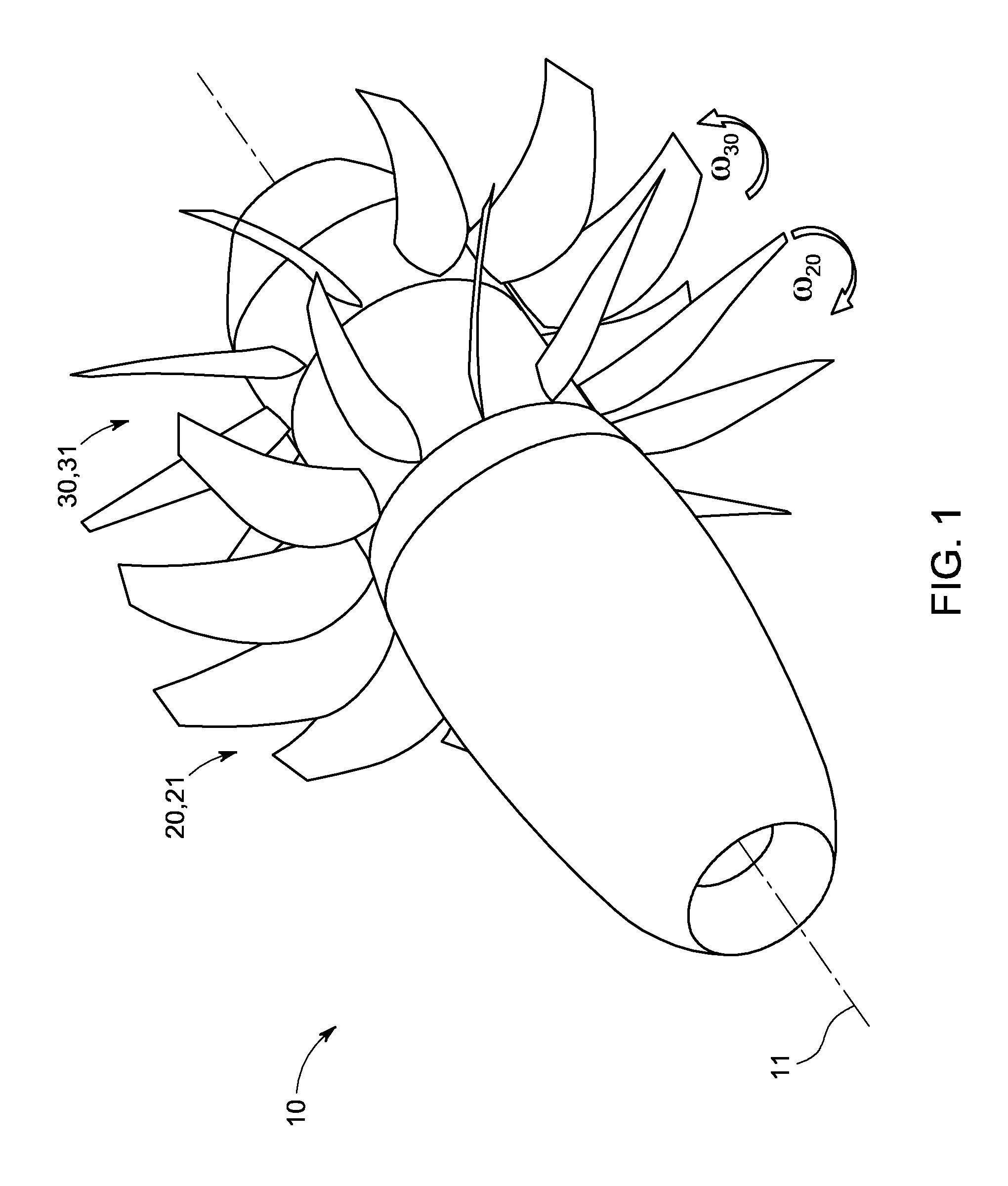
[0016]As used herein, “contra-rotational relationship” means that the airfoil blades of the first and second rotor assemblies are arranged to rotate in opposing directions to each other. It is preferred that the airfoil blades of the first and second rotor assemblies are arranged to rotate about a common axis in opposing directions, and are axially spaced apart along that axis. For example, the respective airfoil blades of the first rotor assembly and second rotor assembly ma be co-axially mounted and spaced apart, with the blades of the first rotor assembly configured to rotate clockwise about the axis and the blades of the second rotor assembly configured to rotate counter-clockwise about the axis (or vice versa).

[0017]By ensuring that the actuator assembly is adapted to be secured to a non-rotating frame, embodiments of the present invention avoid the need for oil transfer bearings that would otherwise he needed if the actuator assembly were itself able to rotate relative to the ...


PUM


Abstract

A pitch control mechanism for an open rotor gas turbine engine is provided, the engine having a first rotor assembly and a second rotor assembly, with a plurality of airfoil blades circumferentially mounted on each rotor assembly, and arranged in contra-rotational relationship to each other. The pitch control mechanism includes an actuator assembly configured to be secured to a non-rotating frame of the engine, the actuator assembly having a first actuator and a second actuator, with the actuator assembly being rotationally isolatable from and couplable to the first and second rotor assemblies such that, in use, an actuation signal from the first or second actuator induces a corresponding desired change in pitch of the airfoil blades of the respective first or second rotor assembly independently of the pitch of the airfoil blades of the second or first rotor assembly.

Description

BACKGROUND OF THE INVENTION[0001]Embodiments of the subject matter disclosed herein relate to a mechanism for enabling independent pitch control of airfoil blades of contra-rotating rotor assemblies. The application is of particular benefit when applied to “open rotor” gas turbine engines.[0002]Gas turbine engines employing an “open rotor” design architecture are known. The open rotor design is essentially a hybrid of conventional turbofan and turboprop gas turbine engines, but providing enhanced fuel efficiency over both conventional engine designs. A turbofan engine operates on the principle that a central gas turbine core drives a bypass fan, the fan being located at a radial location between a nacelle of the engine and the engine core. An open rotor engine instead operates on the principle of having the bypass fan located outside of the engine nacelle. This permits the use of larger fan blades able to act upon a larger volume of air than for a turbofan engine, and thereby helps ...

Claims


Application Information

Patent Timeline
IPC IPC(8): F01D1/26
CPCB64C11/308F01D1/26Y02T50/66F02C9/58B64D2027/005F02K3/072Y02T50/60B64C11/30B64C11/306B64D35/06B64D27/16F02K3/025F05D2220/323F05D2240/30F05D2260/40311
Inventor SZYMANDERA, ALEKSANDER KRZYSZTOF
Owner GE AVIATION SYST LTD
Why Eureka
Try Eureka