
High pressure gas supply system and fuel cell system

a gas supply system and high-pressure technology, applied in the direction of electrical equipment, transportation and packaging, mechanical equipment, etc., can solve the problem of reducing the function of the gas supply portion, and achieve the effect of stable operation

Active Publication Date: 2013-02-28
TOYOTA JIDOSHA KK
View PDF2 Cites 10 Cited by
  • Summary
  • Abstract
  • Description
  • Claims
  • Application Information

AI Technical Summary

Benefits of technology

This invention improves the ability of a system to start up and operate in low temperature environments. The high pressure gas supply system described in this patent is designed to maintain the function of the gas supply functional portion, even in the event of a decrease in its function caused by the low ambient temperature. By exposing the gas supply functional portion to the high-temperature gas in the tank before the start signal, the function can be recovered and stable operation can be achieved from the very beginning of the startup process. The preliminary control portion can perform the preliminary control based on the ambient temperature and the temperature inside the tank, ensuring reliable functioning of the gas supply functional portion even in low temperature environments. This system is simple and cost-effective, with no need for special equipment. The high pressure gas supply system described in this patent provides early stabilization of the operating state during startup in low temperature environments, ensuring stable operation of the fuel cell or other gas supply system.

Problems solved by technology

In this aspect, in a low temperature environment that may cause a decrease in function of the gas supply functional portion arranged in the gas supply line, there is a possibility that the function of the gas supply functional portion may decrease.

Method used


Image

  • High pressure gas supply system and fuel cell system
  • High pressure gas supply system and fuel cell system
  • High pressure gas supply system and fuel cell system

Examples


Embodiment Construction

[0022]Example embodiments of the present invention will be described in greater detail below with reference to the accompanying drawings.

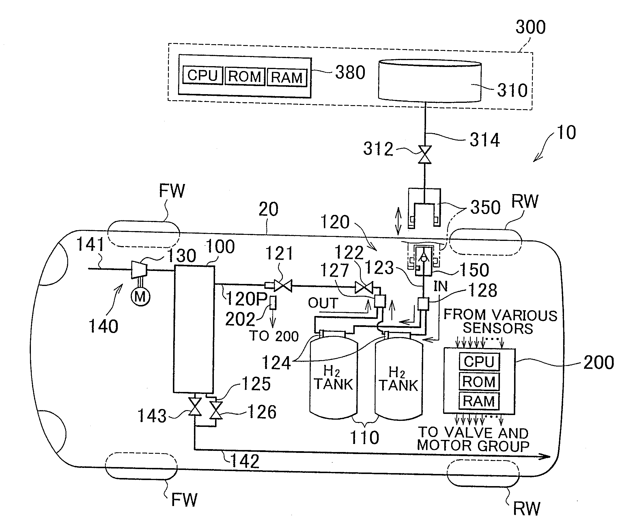
[0023]As shown in FIG. 1, this fuel cell system 10 includes a fuel cell 100, a hydrogen gas supply system 120 that includes two high pressure gas tanks 110, an air supply system 140 that includes a motor-driven compressor 130, a cooling system, not shown, and a control apparatus 200, all provided in a fuel cell vehicle 20. The fuel cell 100 is formed by a stack of power generating modules, each including a membrane electrode assembly (MEA), not shown, in which an anode is joined to one side of an electrolyte membrane and a cathode is joined to the other side of the electrolyte membrane. The fuel cell 100 is positioned under the floor of the vehicle between front wheels FW and rear wheels RW. This fuel cell 100 generates power by inducing an electrochemical reaction between hydrogen in hydrogen gas supplied from the hydrogen gas supply system 120 th...


PUM


Abstract

A fuel cell system (10) includes a pressure decrease valve (121) and a flow control valve (122) provided in a hydrogen supply line (120P) that extends from a high pressure gas tank (110) to a fuel cell (100). A low temperature environment may cause the function of these devices to decrease. Therefore, if the gas temperature inside the high pressure gas tank (110) is higher than the temperature of this low temperature environment and is a temperature at which the decreased function can be recovered, high pressure gas inside the tank is made to flow through the hydrogen supply line (120P) to expose the pressure decrease valve (121) and the like to the relatively high temperature gas before a start signal that starts the system is received.

Description

BACKGROUND OF THE INVENTION[0001]1. Field of the Invention[0002]The invention relates to a high pressure gas supply system that supplies high pressure gas to a gas consuming apparatus, and a fuel cell system provided with this high pressure gas supply system.[0003]2. Description of the Related Art[0004]In recent years, vehicles driven by combustion energy of fuel gas and electric energy generated by an electrochemical reaction of fuel gas have been developed. Fuel gas such as natural gas and hydrogen is stored in high pressure gas tanks provided in these vehicles. Also, stationary fuel cell systems provided with fuel cells that induce an electrochemical reaction of fuel gas as a power source for generating electricity are also becoming more prevalent.[0005]Because stationary fuel cell systems or fuel cell systems for vehicles may be started in a low temperature environment, Japanese Patent Application Publication No. 2005-158426 (JP-A-2005-158426), for example, proposes technology t...

Claims


Application Information

Patent Timeline
IPC IPC(8): H01M8/04
CPCH01M8/04014H01M8/04201H01M8/04253Y02E60/50H01M8/04373H01M8/04731H01M8/04753H01M8/0432F17C2221/012F17C2270/0178F17C2270/0184Y02E60/32
Inventor INAGI, SHUSUKE
Owner TOYOTA JIDOSHA KK
Learn More