Multilayer high density microwells

Active Publication Date: 2013-02-28
RGT UNIV OF CALIFORNIA
View PDF3 Cites 26 Cited by
  • Summary
  • Abstract
  • Description
  • Claims
  • Application Information

AI Technical Summary

Benefits of technology

[0007]In one embodiment, a multilayer high density well array is disclosed in which the density of microwell arrays is increased dramatically. The multilayer high density well array can be used for digital microfluidics to gain the advantage of immovable and well-defined microwell array patterns for real-time observ

Problems solved by technology

Although densities have become high, they are often limited by pattern formation and manufacturing techniques with often limited well height to width aspect ratios on only a single planar surface.
As a result, a large usable area between the microwells is lost depending on the pitch or spacing between adjacent wells.
As the footprint of the microwell size is reduced to accommodate even higher densities, the ratio of usable microwell area to dead space decreases exponentially resulting in eve

Method used


Image

  • Multilayer high density microwells
  • Multilayer high density microwells
  • Multilayer high density microwells

Examples


Embodiment Construction

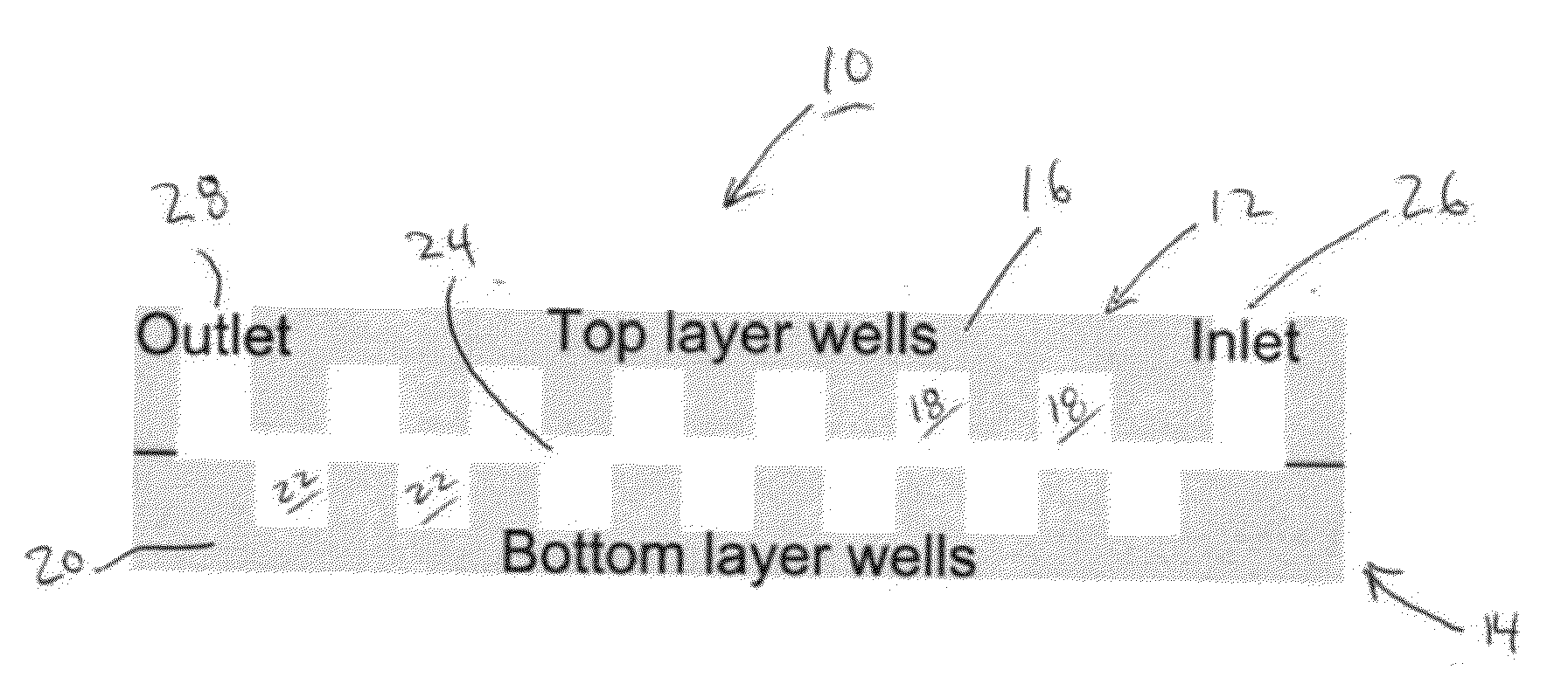
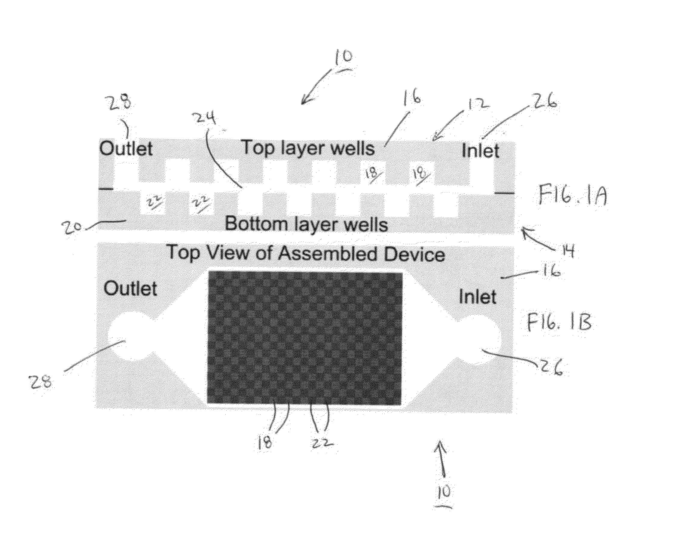
[0021]FIGS. 1A and 1B illustrate side and top views, respectively, of a multilayer well device 10 according to one embodiment. The multilayer well device 10 is illustrated in FIGS. 1A and 1B as containing two (2) layers 12, 14. The upper layer 12 is formed from a first substrate 16 and contains therein an array of wells 18 having a first pattern. The first substrate 16 is preferably made from an optically transparent material which can include, as mentioned below, a polymer-based material. The lower layer 14 is formed from a second substrate 20 and contains therein an array of wells 22 having a second pattern that is complementary to the first pattern. As seen in FIG. 1A, the wells 22 of the second substrate 20 are laterally offset from the corresponding wells 18 of the first substrate 16. The second substrate 20 is also preferably made from an optically transparent material which can be the same as the material used for the first substrate 16.

[0022]The size of the wells 18, 22 may ...


PUM

PropertyMeasurementUnit
Heightaaaaaaaaaa
Heightaaaaaaaaaa

Abstract

A multilayer well device includes a first substrate comprising an array of wells having a first pattern disposed therein and a second substrate comprising an array of wells having a second pattern, complementary to the first pattern disposed therein, wherein the second substrate is secured adjacent to a face of the first substrate. A common channel is interposed between the array of wells of the respective first and second substrates and is coupled to an inlet and an outlet.

Description

RELATED APPLICATION[0001]This Application claims priority to U.S. Provisional Patent Application No. 61 / 525,976 filed on Aug. 22, 2011, which is hereby incorporated by reference in its entirety Priority is claimed pursuant to 35 U.S.C. §119.STATEMENT REGARDING FEDERALLY SPONSORED RESEARCH OR DEVELOPMENT[0002]This invention was made with Government support under Grant No. N66001-1-4003 awarded by the Defense Advanced Research Projects Agency (DARPA). The Government has certain rights in this invention.FIELD OF THE INVENTION[0003]The field of the invention generally relates to microwells and microarrays. More specifically, the field of the invention pertains to high density micro-reactors useful in digital biology applications.BACKGROUND OF THE INVENTION[0004]High density microwell plates or micro-reactors have been fabricated using various methods to form an array of sites or wells within a single surface. Although densities have become high, they are often limited by pattern formati...

Claims


Application Information

Patent Timeline
IPC IPC(8): B01L3/00C12M1/34B23P17/04G01N21/78
CPCB01L3/5027B01L3/5085B01L3/50851B01L2200/027B01L2200/0642B01L2200/0684Y10T436/143333B01L2300/0819B01L2300/0874B01L2300/0887B01L2300/0893B01L2400/0406Y10T29/49826B01L2200/0689
Inventor LEE, ABRAHAM P.HATCH, ANDREW C.
Owner RGT UNIV OF CALIFORNIA
Why Eureka
Try Eureka