Multilayer Antireflection Layer, Method for Producing the Same, and Plastic Lens

a multi-layer anti-reflection and lens technology, applied in the field of multi-layer anti-reflection layer, method for producing the same, and plastic lens, can solve the problems of reducing the scratch resistance, the lens for spectacles disclosed, and still insufficient scratch resistance, and achieves excellent scratch resistance, low environmental load, and the effect of increasing the density of the high refractive index layer

Inactive Publication Date: 2010-04-29
HOYA LENS MFG PHILIPPINES
View PDF23 Cites 24 Cited by
  • Summary
  • Abstract
  • Description
  • Claims
  • Application Information

AI Technical Summary

Benefits of technology

[0006]An advantage of some aspects of the invention is to provide a multilayer antireflection layer that has a grain boundary and has excellent scratch resistance, a method for producing the multilayer antireflection layer, and a plastic lens having the multilayer antireflection layer formed thereon.
[0008]According to the multilayer antireflection layer of the aspect of the invention, the high reflective index layer has a grain boundary, and particles forming the grain boundary have an average particle diameter of 30 nm or less, whereby the high refractive index layer has an increased density to enhance the scratch resistance thereof significantly.
[0012]According to this configuration, the high refractive index layer contains at least one of zirconium oxide, tantalum oxide and niobium oxide, whereby the high refractive index layer can be hardened, and thus such a multilayer antireflection layer can be provided that has both scratch resistance and impact resistance.
[0016]According to the plastic lens of the aspect of the invention, such a plastic lens can be provided that has increased scratch resistance owing to the multilayer antireflection layer formed thereon.
[0019]In the aspect of the invention, the high refractive index layer is formed by a dry film forming method, whereby such a multilayer antireflection layer can be provided that is dense and hard and has excellent scratch resistance, as compared to one formed by a wet method, such as a sol-gel method. It is more effective that not only the high refractive index layer but also the low refractive index layer are formed by a dry film forming method. The dry film forming method is low in environmental load since the dry film forming method does not use a solvent, which is necessarily used in the wet film forming method.

Problems solved by technology

However, the lens for spectacles disclosed in JP-A-2007-279203 is still insufficient in scratch resistance.
The organic substance remaining may prevent the hardness of the thin film from being increased sufficiently, thereby decreasing the scratch resistance thereof.
Upon forming the thin film on a surface of a plastic substrate, in particular, the heating temperature of the gel cannot be sufficiently high, and an organic substance is liable to remain inside the thin film.
Consequently, a thin film that is formed on a surface of a plastic substrate by a wet method, such as a sol-gel method, has considerably low hardness and thus has deteriorated scratch resistance.

Method used


Image

  • Multilayer Antireflection Layer, Method for Producing the Same, and Plastic Lens
  • Multilayer Antireflection Layer, Method for Producing the Same, and Plastic Lens
  • Multilayer Antireflection Layer, Method for Producing the Same, and Plastic Lens

Examples


example 1

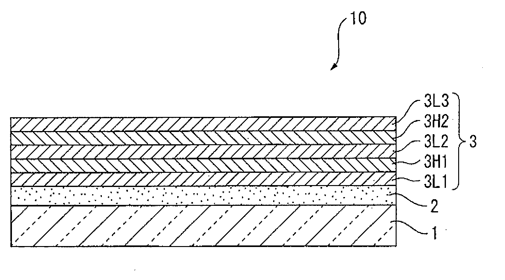
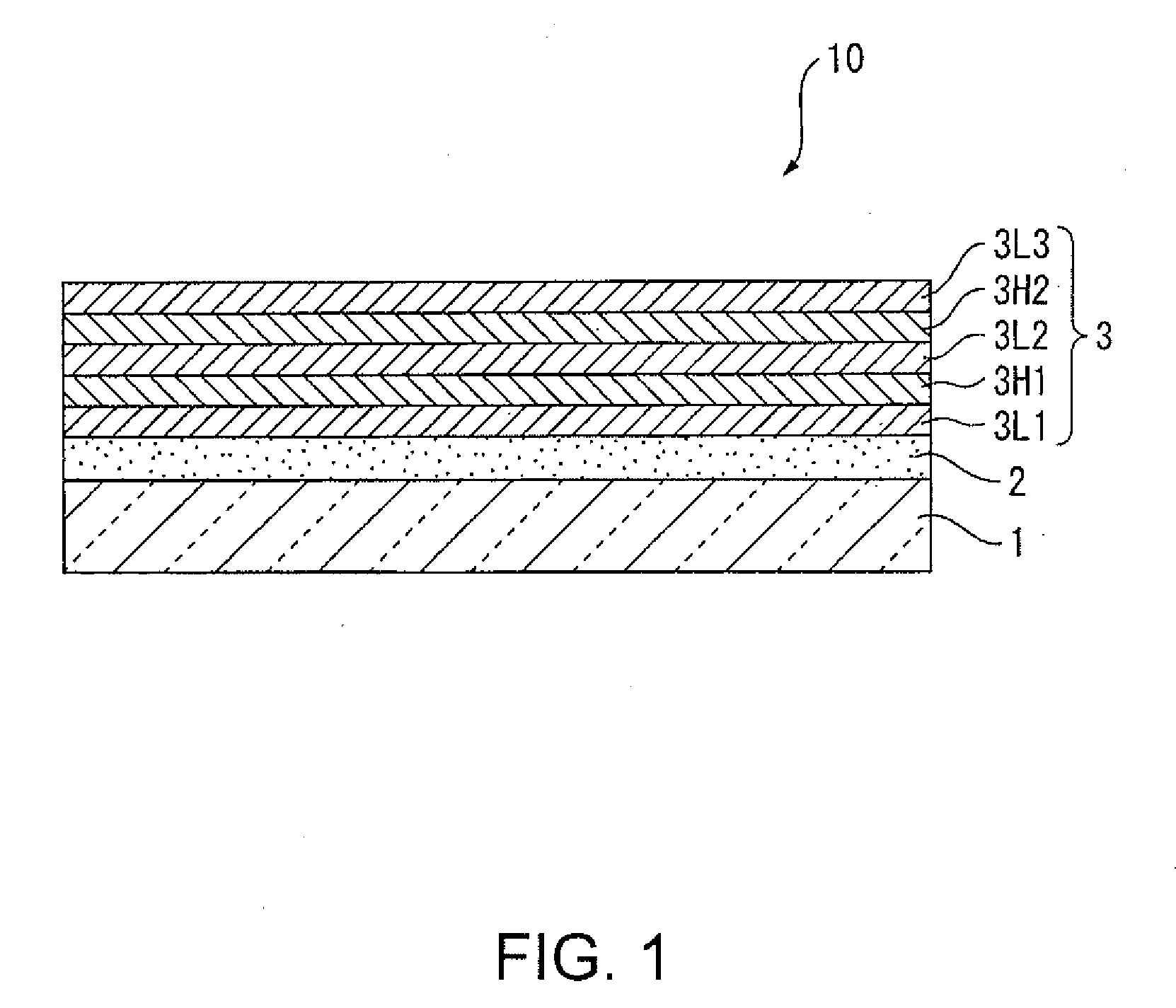
[0066]A plastic lens for spectacles (Seiko Prestige, produced by Seiko Epson Corporation) having a substrate 1 having formed thereon a primer layer and a hard-coat layer 2 was used.

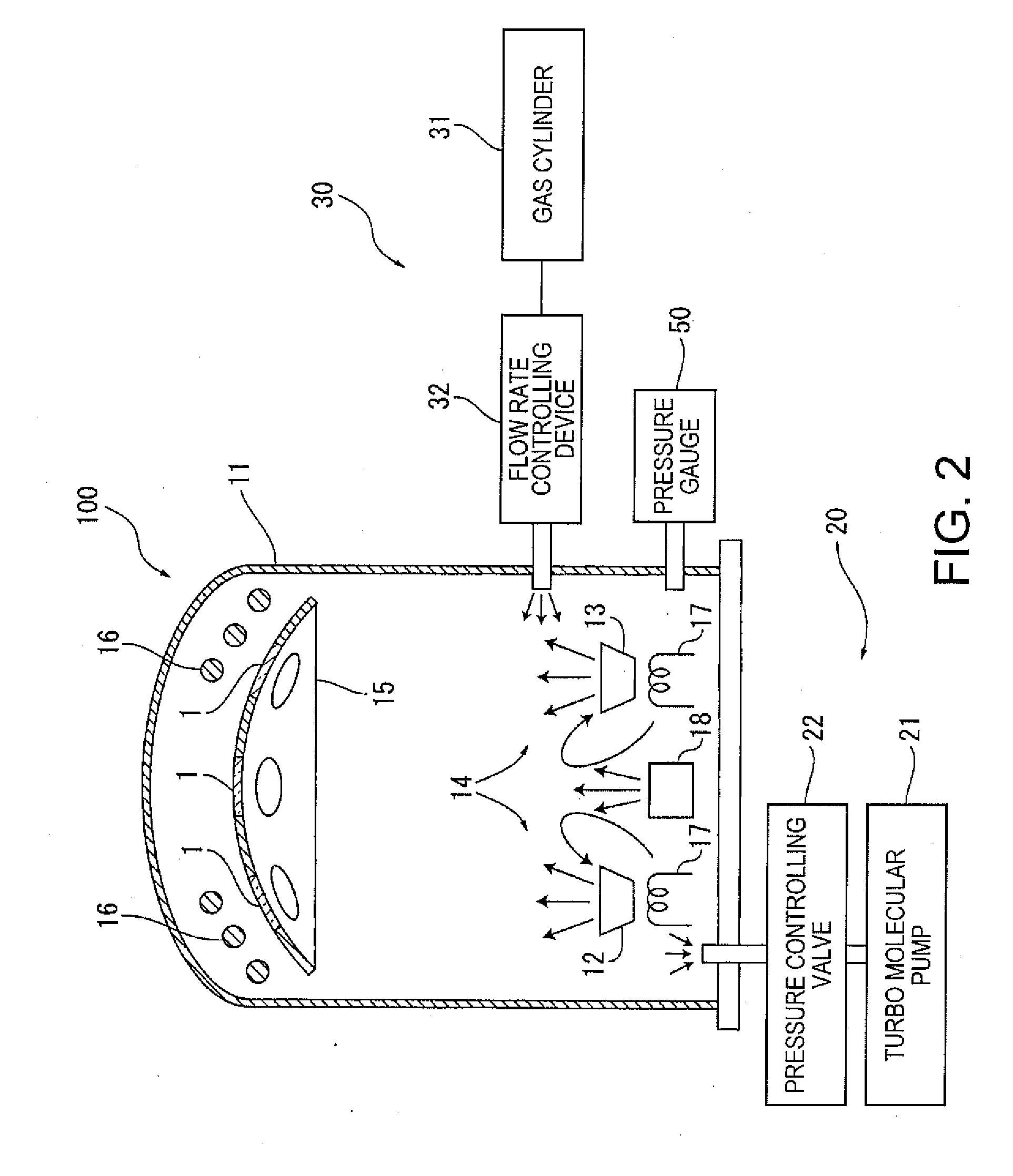
[0067]The plastic lens was degassed in the first chamber, which was not shown in the figure, set at a temperature of 60° C., and was subjected to ion cleaning for 2 minutes in the second chamber (vacuum deposition apparatus 100) under conditions of an acceleration voltage of 500 V, an acceleration current of 250 mA, a bias current of 380 mA and a flow rate of an oxygen introducing gas of 20 sccm.

[0068]The treatments were performed for cleaning the surface of the substrate, thereby enhancing adhesion between the substrate and the antireflection film.

[0069]The second chamber was then evacuated to high vacuum with a vacuum degree of 6.0×10⁻⁴ Pa, and silicon oxide was vapor-deposited as the first layer. Thereafter, a zirconium oxide layer was deposited as the second layer by ion assisted vapor deposition at a...

example 2

[0075]The same procedures as in Example 1 were performed except that the conditions for ion assisted deposition for forming zirconium oxide layers as the second and fourth layers were changed to an acceleration voltage of 600 V, an acceleration current of 250 mA, a bias current of 375 mA, which was 1.5 times the acceleration current, and 20 sccm of oxygen gas introduced.

[0076]The period of time required for the sequence of operations for forming the layers, i.e., the operations of from degassing operation in the first chamber through formation of an antifouling layer on the opposite surface, was 45 minutes.

example 3

[0077]The same procedures as in Example 2 were performed except that the vacuum degree in the second chamber upon starting formation of layers was changed to 1.5×10⁻⁴ Pa.

[0078]The period of time required for the sequence of operations for forming the layers, i.e., the operations of from degassing operation in the first chamber through formation of an antifouling layer on the opposite surface, was 4 hours.


PUM

PropertyMeasurementUnit
Nanoscale particle sizeaaaaaaaaaa
Particle diameteraaaaaaaaaa
Timeaaaaaaaaaa

Abstract

A multilayer antireflection layer includes a high refractive index layer and a low refractive index layer that are laminated alternately, the high reflective index layer having a grain boundary, and particles forming the grain boundary having an average particle diameter of 30 nm or less.

Description

BACKGROUND[0001]1. Technical Field[0002]The present invention relates to a multilayer antireflection layer containing a, high refractive index layer and a low refractive index layer laminated alternately, a method for producing the multilayer antireflection layer, and a plastic lens having the multilayer antireflection layer formed on a substrate.[0003]2. Related Art[0004]A plastic lens for spectacles generally has on the surface thereof a hard-coat layer for preventing scratches and an antireflection layer. The hard-coat layer is formed on the surface of the lens substrate, and the antireflection layer is formed on the surface of the hard-coat layer. A so-called multilayer antireflection layer, which contains substances having different refractive indices laminated alternately, is generally used as the antireflection layer. Known examples of the multilayer antireflection layer include a multilayer antireflection layer having a high refractive index layer that forms a grain boundary...

Claims


Application Information

Patent Timeline
IPC IPC(8): G02B1/11B32B7/02B05D5/06B82Y20/00B82Y40/00C23C14/08C23C14/48G02B1/115G02B1/14G02B1/18G02C7/00G02C7/04
CPCG02B1/105Y10T428/24942G02B1/115G02B1/14
Inventor FUKUI, TOMOHITONISHIMOTO, KEIJINOGUCHI, TAKASHI
Owner HOYA LENS MFG PHILIPPINES
Why Eureka
Try Eureka