
Battery management system, method and battery

Active Publication Date: 2013-03-07
PAG
View PDF3 Cites 26 Cited by
  • Summary
  • Abstract
  • Description
  • Claims
  • Application Information

AI Technical Summary

Benefits of technology

This patent is about an improved electrical battery system that can connect multiple batteries together, even if they exceed the maximum safe power rating of a device. This system can provide a high capacity power supply for extended periods of time, exceeding the limitations of previous devices and batteries. The batteries are connected in parallel to increase overall battery capacity. This allows for more powerful and durable battery arrangements.

Problems solved by technology

For instance, High Definition and Very High Definition cameras and other such equipment require much more power than older Standard Definition cameras.
Whilst it is possible to make very high capacity batteries which are able to deliver sufficient power for such applications, very high capacity batteries suffer from inherent safety issues.
Particularly, incorrect coupling of such batteries, malfunction of the electrical device or damage to the batteries can cause rapid discharge of the batteries and the risk of serious thermal events.
For instance, current aviation regulations in some countries limit the transportation of batteries in passenger aircraft to those having a capacity of less than 100 Watt-hours.
This limits device operating time available from such batteries, particularly in the case of high consumption devices such as High and Very High Definition cameras.
However, even doubling battery capacity in this manner still does not provide an adequate operating time for some applications.

Method used


Image

  • Battery management system, method and battery
  • Battery management system, method and battery
  • Battery management system, method and battery

Examples


Embodiment Construction

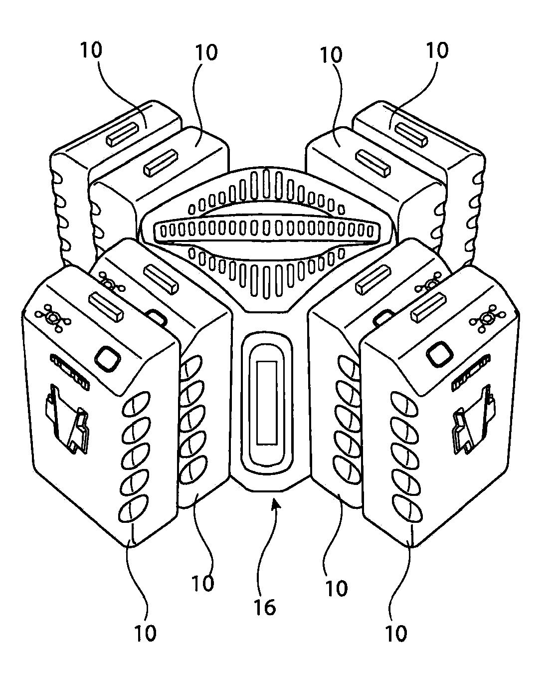
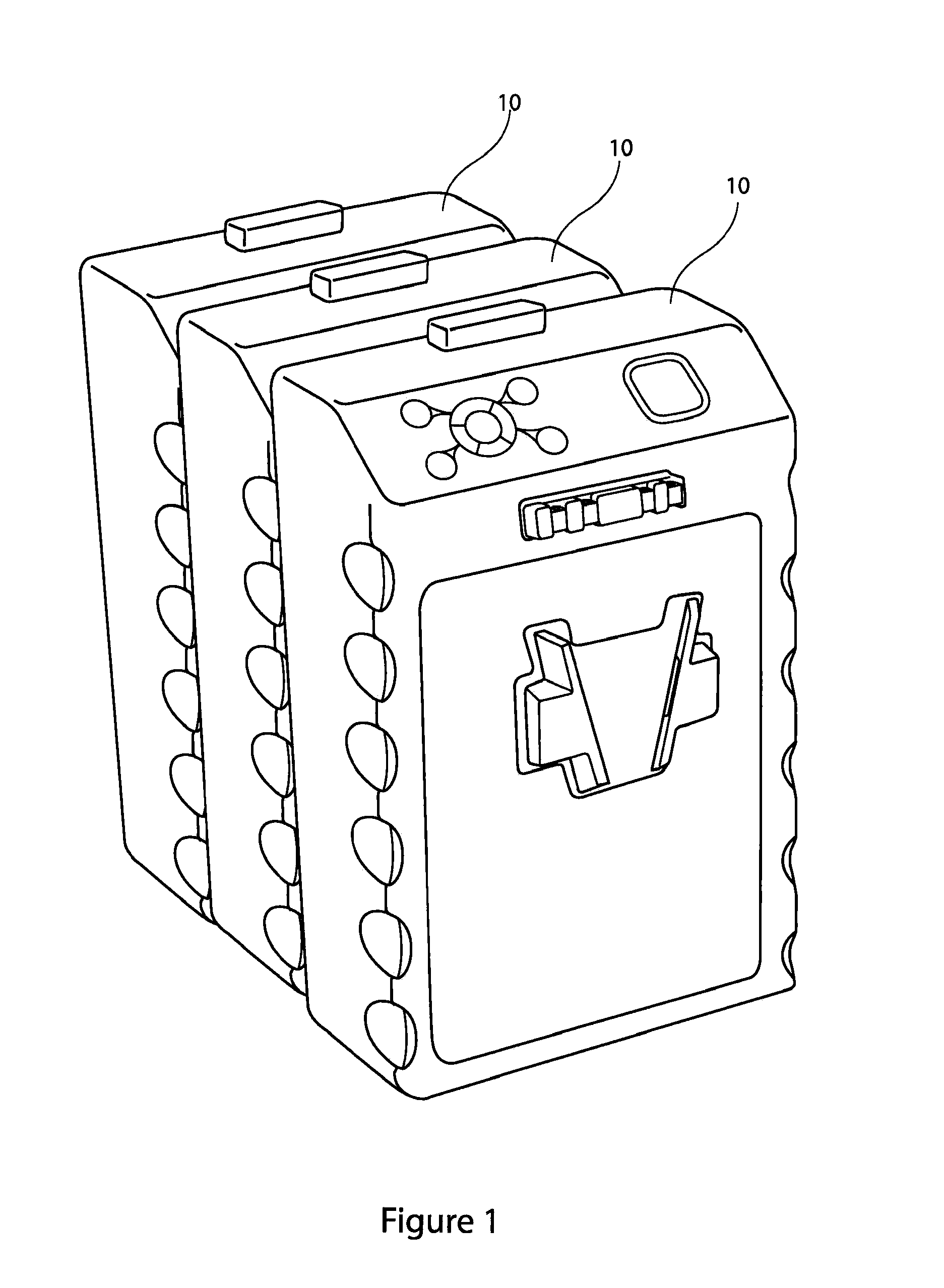
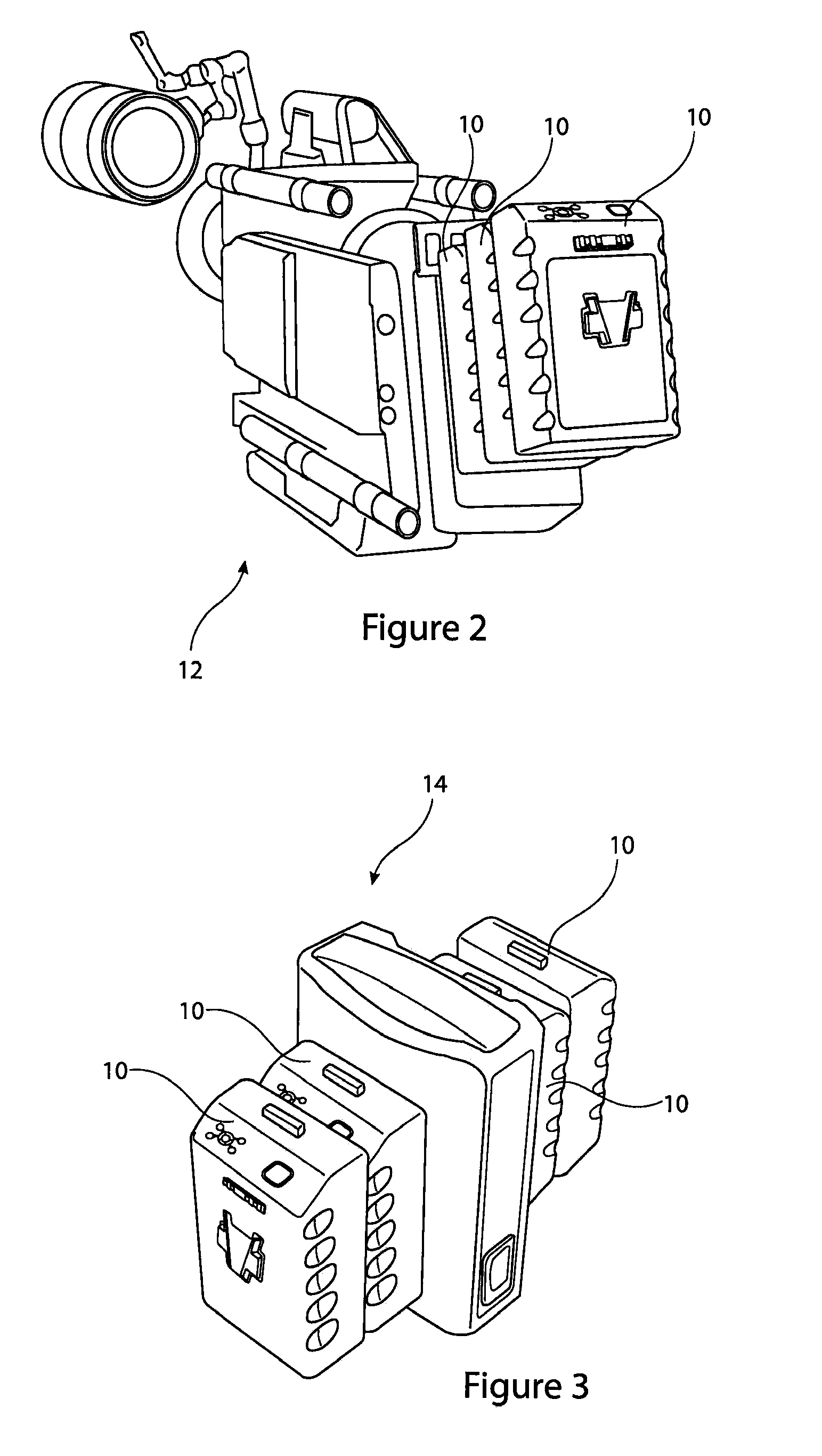
[0032]Referring first to FIG. 1, the teachings disclosed herein are directed to coupling a plurality of batteries together in a stack in order to increase the capacity of a battery-based power supply to an electrical device. The stack can provide greater current to the device and / or can power the device for a greater length of time than can a single battery. This improvement can be achieved even with batteries having a relatively low capacity or current rating.

[0033]With reference to FIG. 1, there are shown three batteries 10, which in this example are identical in their characteristics, coupled together mechanically and electrically in parallel. The couplings, therefore, are such that the potential difference across the battery terminals remains the same but the total current rating of the batteries is, in this example, multiplied threefold. Other embodiments may provide for electrical coupling of batteries in series in order to increase potential difference.

[0034]The mechanical co...


PUM


Abstract

A battery management system includes a master control unit coupled to a plurality of batteries, at least one battery status unit providing data on the status the batteries and a power determination unit providing a measure of the power draw required from the batteries. The master control unit controls the batteries to activate only the number to meet the required power draw. The power determination unit can determine the maximum safe power to a device coupled to the batteries, the master control unit then activating a number of batteries having a combined power capacity not exceeding the safe maximum power. The system allows for a large number of batteries to be coupled to an electrical device and for these to be controlled so as not to produce a current which is too high for the device.

Description

FIELD OF THE INVENTION[0001]The present invention relates to a battery management system, to a method of controlling the operation of a plurality of electrical batteries, as well as to an electrical battery which is operable in, that is suitable for, a battery management system and method as taught herein.BACKGROUND OF THE INVENTION[0002]There is a growing need for higher capacity battery technology, particularly for powering increasingly complex electrical devices, as well as for powering larger devices conventionally powered by other energy sources, such as fuel. For instance, High Definition and Very High Definition cameras and other such equipment require much more power than older Standard Definition cameras. Similarly, there is a desire and need to power vehicles from an electrical source rather than using fossil fuels.[0003]Whilst it is possible to make very high capacity batteries which are able to deliver sufficient power for such applications, very high capacity batteries ...

Claims


Application Information

Patent Timeline
IPC IPC(8): H02J1/00H01M50/296
CPCH02J1/10H02J7/0021H02J7/0045H02J7/34H01M2/10H01M2010/4271H01M2/1016H01M2/1061H01M2/1077H01M2/30H01M10/42H01M2/1011Y02T10/70Y02E60/10H01M50/256H02J7/0013H02J7/0047H01M50/296H02J7/0063H02J7/0068H02J7/00
Inventor LAVENDER, JOHN PAUL
Owner PAG
Learn More