Thermal Apparatus

Active Publication Date: 2013-03-07
LEE CHOON KEE
View PDF2 Cites 17 Cited by
  • Summary
  • Abstract
  • Description
  • Claims
  • Application Information

AI Technical Summary

Benefits of technology

[0047]In one embodiment, the goal of hyperthermia by the present invention is to achieve temperature of a target area high enough to make tissue of said target area die but low enough to avoid damage to normal tissue adjacent to said target area over a range of duration, which is between 42° C.˜45° C. of said target area. When temperature differences between a non-target area and target area under therapy are monitored, the goal of said temperature differences is to achieve 6° C.˜8° C. higher temperature at the target area under therapy.
[0048]In another embodiment, the present inventi

Problems solved by technology

Drawbacks of the radiofrequency ablation include need of correct positioning of needle in the center of the target tissue, heat sink effect of adjacent blood vessels, small treatment volume, increasing impedance of the target tissue during therapy thereby progressively decreasing conductivity, inability to monitor temperature during therapy and occasional burn at a skin-to-ground transition site.
Yet temperature may not be monitored real-time during treatment.
Size of a probe that houses antenna may be larger than that of radiofrequency probe, and selective heating of blood vessels may produce an increased risk of thrombosis of major blood vessels.
These multi-stage procedures increase chances of technical failure and also make the size of the sheath with applicator much larger than those of radiofrequency and of microwave ablation.
Hyperthermia with magnetic materials under alternating electromagnetic current was developed first in 1957 yet its widespread clinical use was hindered by technical limitations such as uncertain distribution of magnetic materials in a target area, need to place magnetic materials manually by needle injection or surgery, local tissue discomfort under high electromagnetic field strength due to the boundary effects, and difficulties in

Method used


Image

  • Thermal Apparatus
  • Thermal Apparatus
  • Thermal Apparatus

Examples


Example

DETAILED DESCRIPTION OF THE DRAWINGS

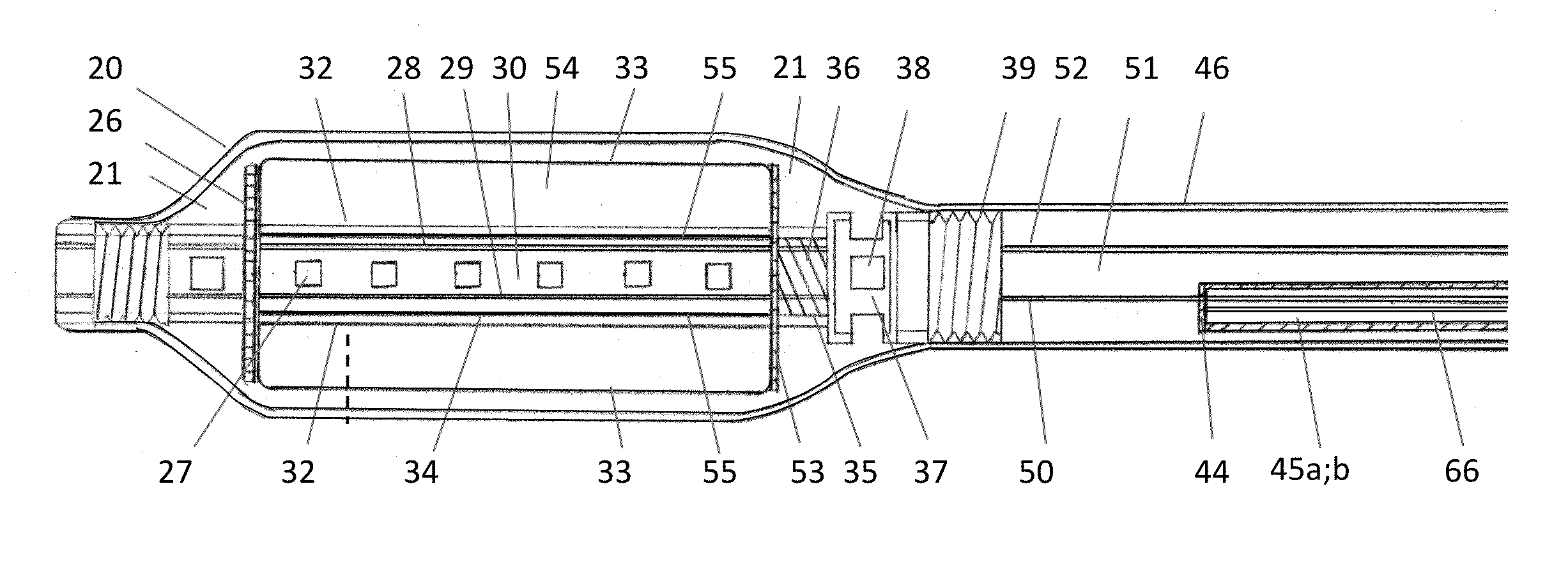
[0071]As described below, the present invention provides a number of devices and methods of use. It is to be understood that the descriptions are solely for the purposes of illustrating the present invention, and should not be understood in any way as restrictive or limited. Embodiments of the present invention are preferably depicted with reference to FIGS. 1 to 18, however, such reference is not intended to limit the present invention in any manner. The drawings do not represent actual dimension of devices, but illustrate the principles of the present invention.

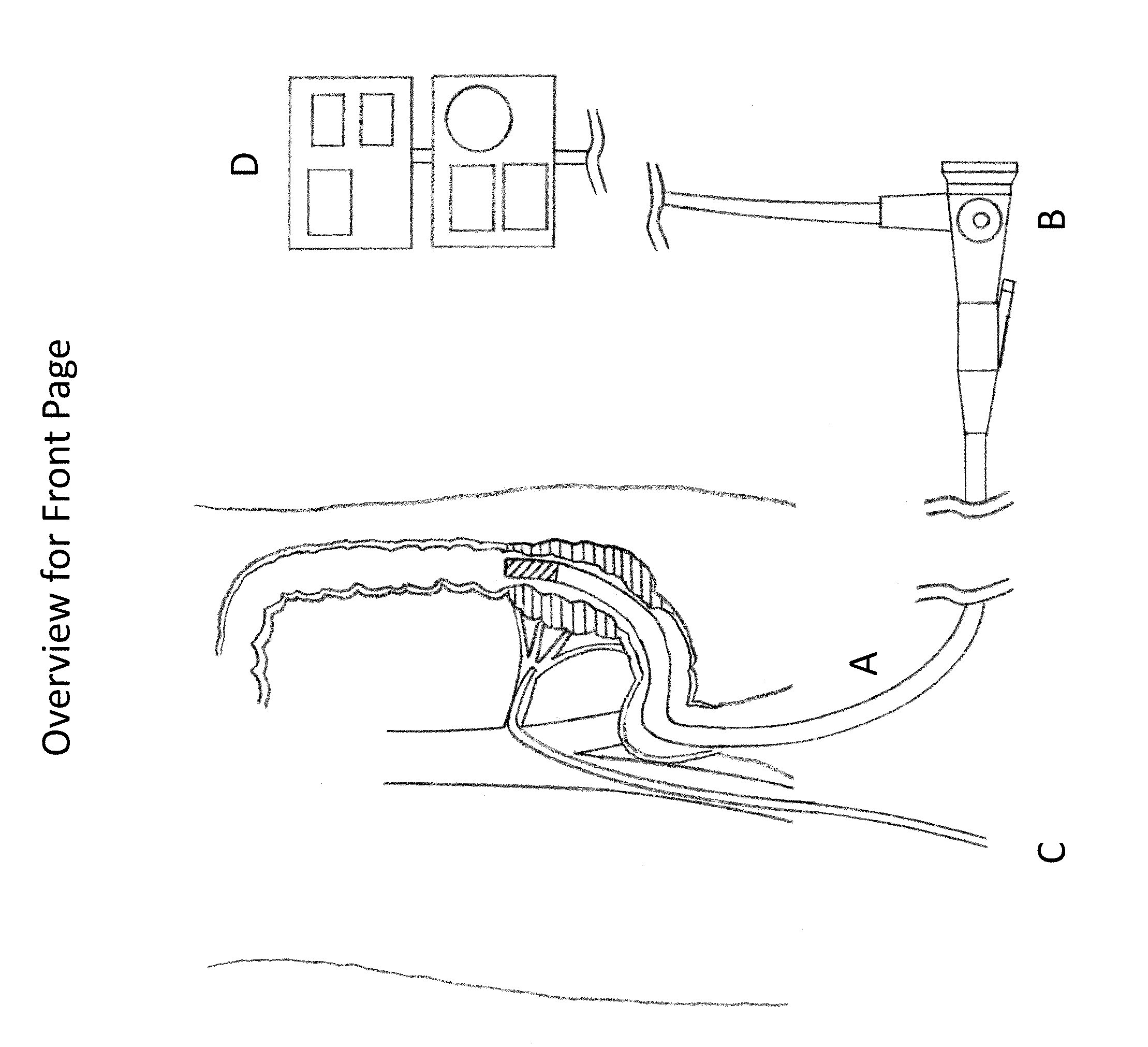
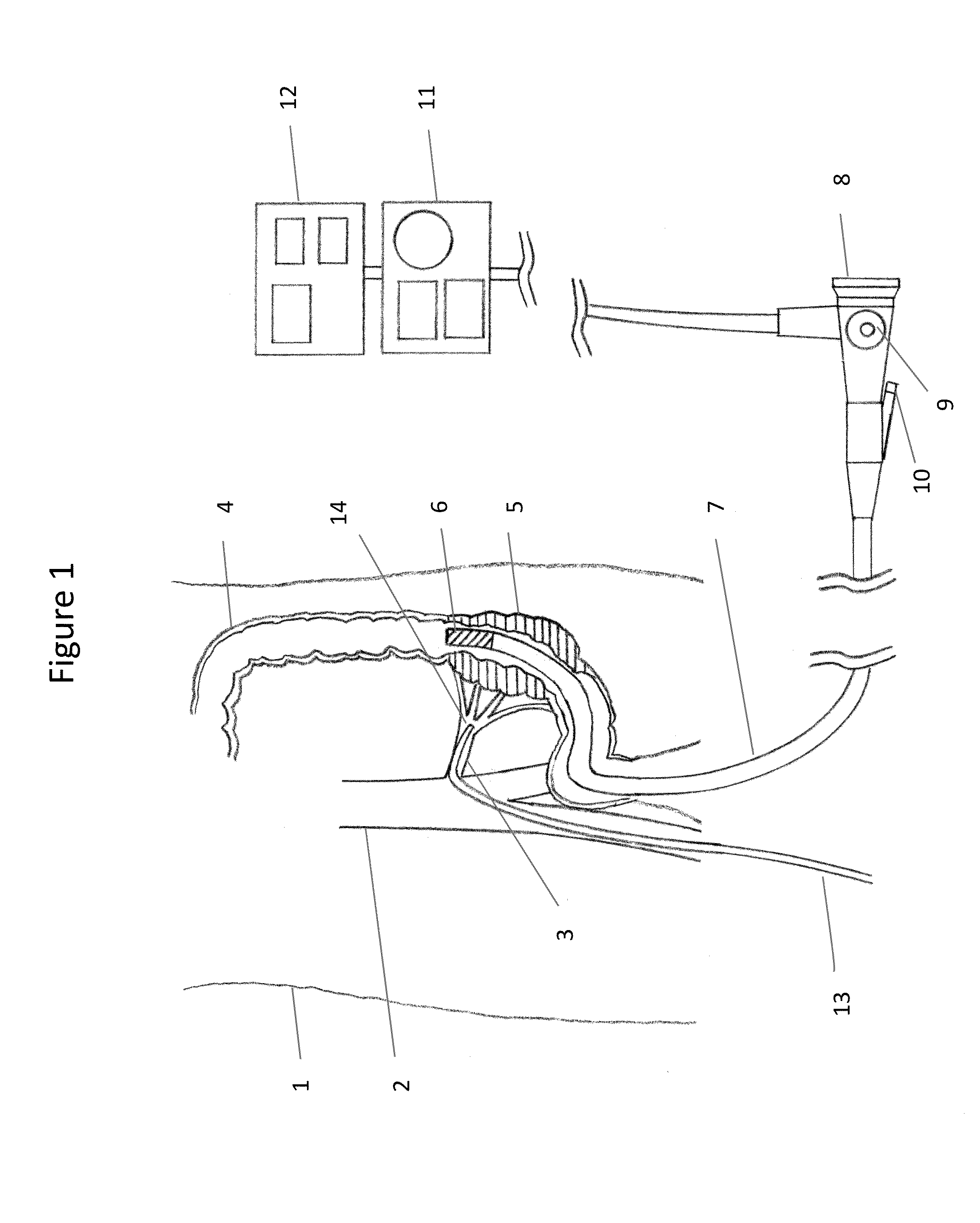
[0072]The overview illustrates a schematic overview of an example of placement of a flexible tubular device A with an electromagnetic assembly of a distal end in a lumen of an intestine via a fiberoptic system B, and of a central vascular catheter C in one branch of arteries leading up to a target area. The flexible fiberoptic tubular device is connected to a power and control assembly D....


PUM


Abstract

Provided herein are an apparatus and methods to induce electromagnetic field in biologic tissue for thermal therapy. The apparatus comprises electromagnetic devices fitted to be releasably deployed inside a body, magnetic materials to be deployed in a body, and a magnetic centrifuge machine. An electromagnetic device includes a controllably flexible fiberoptic tubular device with a magnetic-flux-controlled electromagnetic assembly on its distal end. The electromagnetic device receives direct or alternating electric current. Implanted particulate magnetic materials in close proximity to said electromagnetic assembly form reversible magnetic vascular mold in target blood vessels by static magnetic field produced by direct electric current to said electromagnetic assembly. Implanted magnetic materials generate heat by alternating magnetic field induced by alternating electric current to said electromagnetic assembly. A magnetic centrifuge machine removes magnetic materials from blood by centrifugation under static magnetic field after completion of thermal therapy.

Description

TECHNICAL FIELD[0001]The present invention relates generally to the field of treating tissue by high temperature. More specifically, the present invention provides an apparatus and methods to concentrate magnetic materials in a target area and to treat tissue of the target area in a lumen or a cavity of a body by heat energy induced by alternating magnetic field.BACKGROUND OF THE INVENTION[0002]Traditional ways in medicine to eliminate abnormal tissue or cells include surgery, chemotherapy, irradiation or combination of these. For radiation, both ionizing and non-ionizing types have been developed and successfully used for a range of abnormal tissues from overgrown blood vessels to pre-cancerous tissues to frank cancer. Ionizing radiation uses high energy particles enough to ionize atoms in a matter it passes through. It includes beta ray, x ray, gamma ray and neutron. Clinical application of ionizing radiation has been well developed to a point that it can be delivered to a specifi...

Claims


Application Information

Patent Timeline
IPC IPC(8): A61M1/36A61M5/44A61F7/12
CPCA61M1/3693A61N1/406A61M5/44A61M1/369A61M1/3618A61F7/12A61N2/00A61B1/00
Inventor LEE, CHOON KEE
Owner LEE CHOON KEE
Why Eureka
Try Eureka