Method And System For Position Determination Using RFID Devices

Active Publication Date: 2013-03-07
TRIMBLE NAVIGATION LTD
View PDF4 Cites 60 Cited by
  • Summary
  • Abstract
  • Description
  • Claims
  • Application Information

AI Technical Summary

Benefits of technology

[0012]Numerous benefits are achieved using the present invention over conventional techniques. For example, in an embodiment according to the present invention, RFID technology is used in combination with photogrammetry, laser technology, or an electronic distance measurement technology to determine a location of a rail trolley. Embodiments of the present invention can measure the distance from a rail trolley to a known location of a structure associated with a railway (e.g., a pile that supports a catenary), which has accurate survey coordinates to determine a location of the trolley as a function of time. As described throughout the present specification, a passive RFID tag can include the survey coordinates in memory for use in determining the coordinates of the rail trolley on the track. Another benefit provided by embodiments of the present invention is the ease of saving and retrieving information from RFID tags in comparison with conventional technologies. In some implementations, RFID tags can be installed along the rail line during construction, with the surveying team storing location information in the RFID tags during construction or at a later time. Moreover, embodiments of the present invention provide location information that can be easily read and used by general railway maintenance teams.
[0013]From the application perspective, by utilizing RFID tags in a rail trolley environment, embodiments of the present invention provide productivity improvements in relation to conventional techniques. In some embodiments, the trolley is able to

Problems solved by technology

These vehicles, which can be referred to as track geometry trolleys, are typically expensive to purchase as well

Method used


Image

  • Method And System For Position Determination Using RFID Devices
  • Method And System For Position Determination Using RFID Devices
  • Method And System For Position Determination Using RFID Devices

Examples


Embodiment Construction

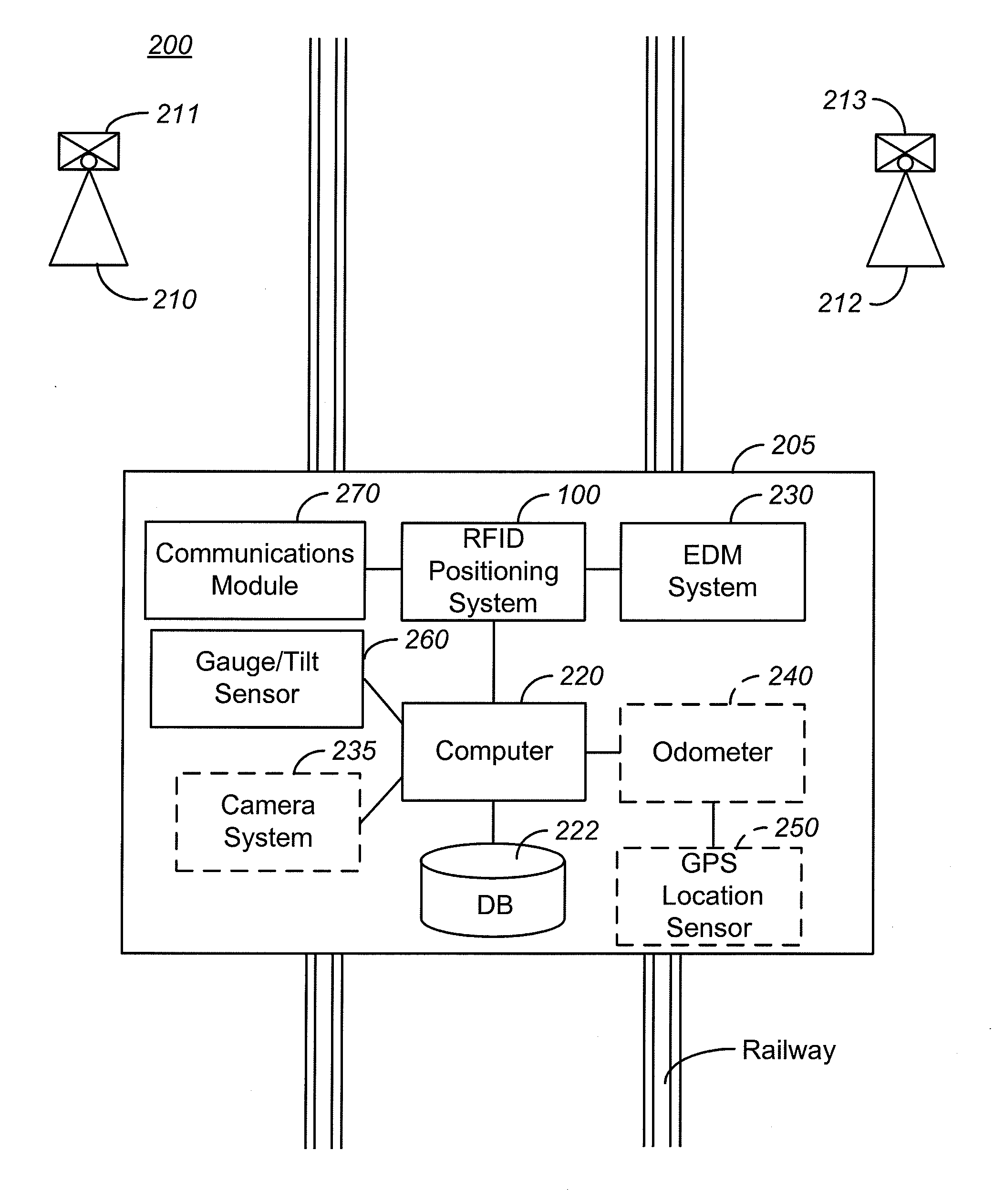
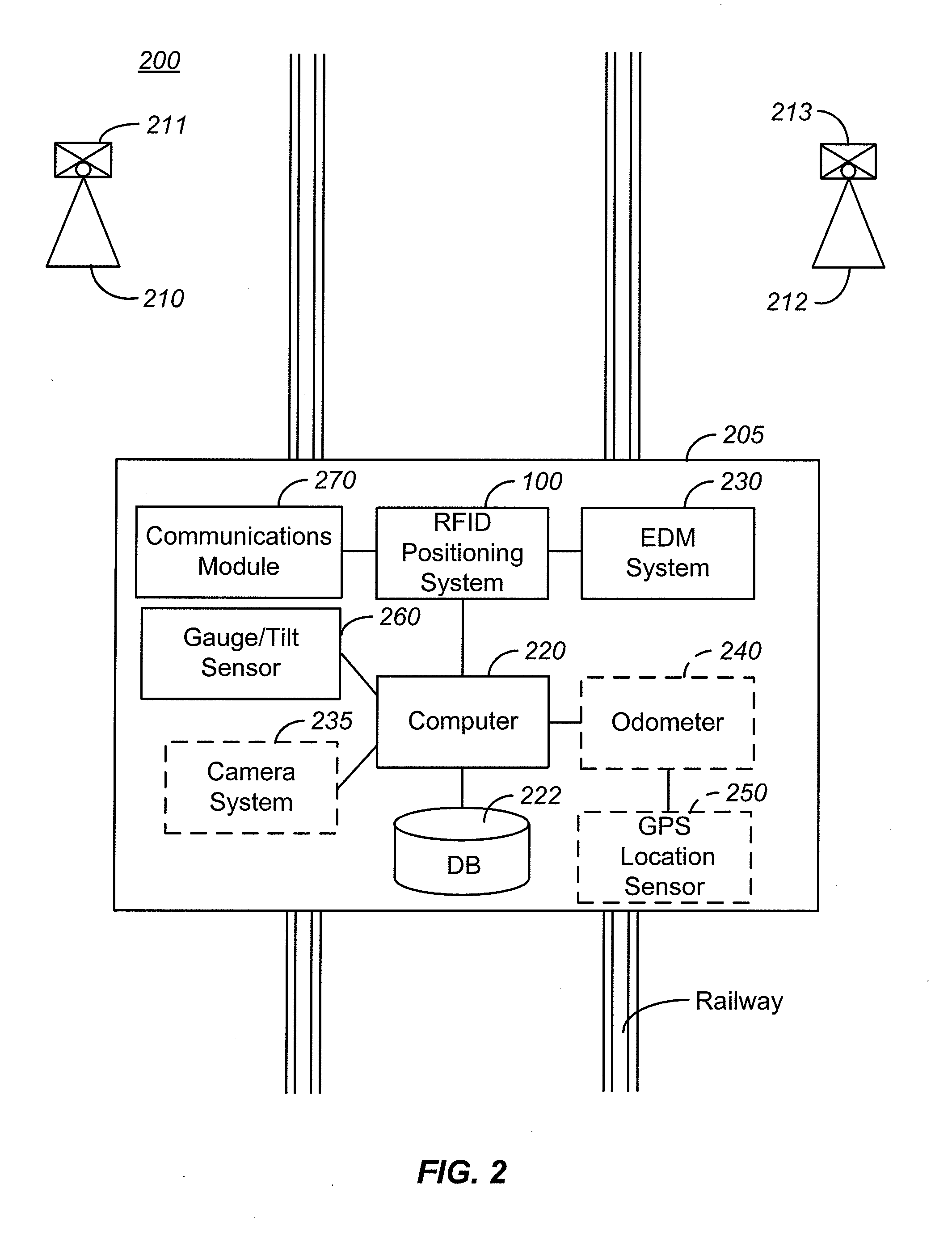
[0024]Although track measurement trolleys can provide information on the gauge and tilt of the track, they are limited in their ability to provide absolute coordinates for the position of the trolley as a function of position along the track. Typically, the trolley will be baselined in a train station and the relative position of the trolley will be measured using a wheel or rotation of the trolley's wheels to measure the mileage accumulated by the trolley as it moves along the track. Slippage of the wheel results in errors in the measurement of the position of the trolley, which can accumulate as the trolley moves farther and farther from the station.

[0025]In order to provide for increased resolution in measuring the position of the trolley as a function of time as it moves down the rail line, a GPS system can be included as equipment on the trolley, enabling accurate position measurement in many conditions. However, GPS systems are typically expensive and fragile. Additionally, wh...


PUM


Abstract

A method of determining a gauge and a tilt of a rail track at a location includes providing a rail trolley including a processor, a memory coupled to the processor, an RFID reader, a gauge sensor, and a tilt sensor and positioning the rail trolley on the rail track at the location. The method also includes interrogating one or more RFID tags positioned along the rail track and determining, using the processor, a fixed location associated with each of the one or more RFID tags. The method further includes determining, using the processor, the location of the rail trolley in relation to the fixed locations associated with each of the one or more RFID tags and determining the gauge and tilt of the rail track at the location of the rail trolley.

Description

CROSS-REFERENCES TO RELATED APPLICATIONS[0001]The following two regular U.S. patent applications (including this one) are being filed concurrently, and the entire disclosure of the other application is incorporated by reference into this application for all purposes:[0002]Application Ser. No. ______, filed on ______, entitled “Method and System for Position Determination Using RFID Devices ” (Attorney Docket No. 89730-796519); and[0003]Application Ser. No. ______, filed on ______, entitled “______” (Attorney Docket No. TANK310).BACKGROUND OF THE INVENTION[0004]Track recording vehicles have been used to measure different attributes of a railway track. These vehicles, which can be referred to as track geometry trolleys, are typically expensive to purchase as well as to operate. As a result, railway maintenance staff typically only inspect rail lines at infrequent intervals. Increases in the frequency and accuracy of track measurements are desirable since they may lead to improved rail...

Claims


Application Information

Patent Timeline
IPC IPC(8): G06F15/00G06K7/01
CPCB61L25/025B61L25/026G01S5/0018G01C15/008G01S17/08B61L23/047
Inventor AMOR, MIGUELHOLMGREN, MARTIN
Owner TRIMBLE NAVIGATION LTD
Why Eureka
Try Eureka