Supersaturated Fluid Degassing

a fluid degassing and supersaturated technology, applied in liquid degasification, membranes, separation processes, etc., can solve the problems of uneconomical otherwise feasible use of expensive reagents and techniques, undesirable use of vacuum pumps, and undesirable use of pumping systems directly contacting the reagent pathway, so as to prevent solvent concentrations from building up sufficiently, the effect of minimizing condensation potential

Active Publication Date: 2013-03-14
IDEX HEALTH & SCI
View PDF6 Cites 21 Cited by
  • Summary
  • Abstract
  • Description
  • Claims
  • Application Information

AI Technical Summary

Benefits of technology

[0022]As illustrated above, in the example case when the inner tube is manufactured from Teflon® AF with a wall thickness of 125 microns wherein the barrer value for water is 4×10³ and for oxygen and nitrogen are 0.9 and 0.4×10² respectively, the permeance is 32 GPU for water vapor, 7.2 GPU for oxygen, and 3.2 for nitrogen. In an example outer shell having a wall thickness of 380 microns and a barrer value of about 3.5×10⁷, the permeance is about 90,000 GPU without accounting for the difference of surface area in which the outer shell has a larger surface area per unit length than the inner conveyance member. Thus, the limit of permeability is the solution-diffusion of air and vapor through the wall of the inner tube. It can be seen that the diffusion rate through the wall of the outer shell is at least 4 or 5 orders of magnitude higher than the diffusion rate of any vapor permeating through the wall of the inner tube membrane comprised of, for example, Teflon® AF. The excess exchange with the atmosphere for similar porous wall thicknesses is the ratio of the inner surface areas of both tubes. In an example embodiment, the inside diameter of the inner tube is 0.85 mm and the inside diameter of the outer shell is approximately 2 millimeters. Hence the diffusion rate from the outer shell is preferably at least 2.2 times greater than pure gas diffusion through the inner tube in order to maintain a clear degassing chamber. Given the relative characteristics of the inner tube and outer shell, a more restrictive limit is imposed on the rate at which air and water vapor diffuse through the wall of the inner tube by the diffusion rate of gas through the water (liquid), in comparison to the permeation rate through the wall of the outer shell. Thus, in the above example embodiment, the ratio of gas flow through the inner tube into the degassing chamber to the gas flow through the wall of the outer shell is at least 1:2.2. As the purpose of the outer shell is both to protect the inner tube and to allow near-free exchange of vapor with atmosphere and thus prevent solvent concentrations building sufficiently to allow condensation upon temperature change, the present arrangement minimizes condensation potential for aqueous and solvent systems alike.

Problems solved by technology

Microanalyses generally use small amounts of reagents and thus allows the use of costly reagents and techniques not otherwise economically feasible.
While each of these devices may at least optionally employ a vacuum to degas the fluid passing therethrough, the goals of the microfluidic system designer may be such that the use of a vacuum pump is undesirable.
Additionally, the design goals of the same designer may be such that the use of a pumping system which directly contacts the reagent pathway is also undesirable.
Such reagent bags are single-use, they contribute to the cost of every analysis, and may be limited to short exposures to pressurization by gas before the contents become supersaturated with the pressurization gas.
Mechanical pressurized systems are not widely used due to sealing considerations between the driving means and the fluid.
As described in U.S. Pat. No. 4,133,767, outgassing of atmospheric pressurized liquids was found to be limited if such solvents were sparged of dissolved atmosphere using helium as a sparging gas.
However, other concerns regarding the use of helium arise.
First, helium quickly supersaturates the pressurized fluid, and although of limited solubility, helium nevertheless forms bubbles when the fluid is exposed to a lower pressure.
Secondly, helium is of limited availability, expensive and requires bulky containers.
Thirdly, many of the desired chemical reactions in microfluidic systems are accelerated or inhibited by the exclusion of oxygen that may be brought about by helium or other inert gas pressurization.
Conventional degassing systems do not well accommodate the transport and condensation of the liquid vapors permeating through the membrane into the space between the membrane and the outer impermeable shell (the degassing chamber).
Without active removal of the vapors accumulating in the degassing chamber, temperature changes may cause a build-up of condensate within the degassing chamber.
Condensate build-up can also cause mechanical interference with the action of the vacuum pump.
While conventional degassing systems employ mechanisms and / or processes through which condensate may be removed from the degassing chamber, certain degassing applications do not employ the mechanisms of conventional systems necessary to purge and / or dilute condensate vapors in the degassing chamber.
Moreover, a mechanism for introducing external gas flow to the permeate side of the membrane may not be available or desired.

Method used


Image

  • Supersaturated Fluid Degassing
  • Supersaturated Fluid Degassing
  • Supersaturated Fluid Degassing

Examples


Embodiment Construction

[0026]The objects and advantages enumerated above together with other objects, features and advances represented by the present invention will now be presented in terms of detailed embodiments described with reference to the attached drawing figures which are intended to be representative of various possible configurations of the invention. Other embodiments and aspects of the invention are recognized as being within the grasp of those having ordinary skill in the art.

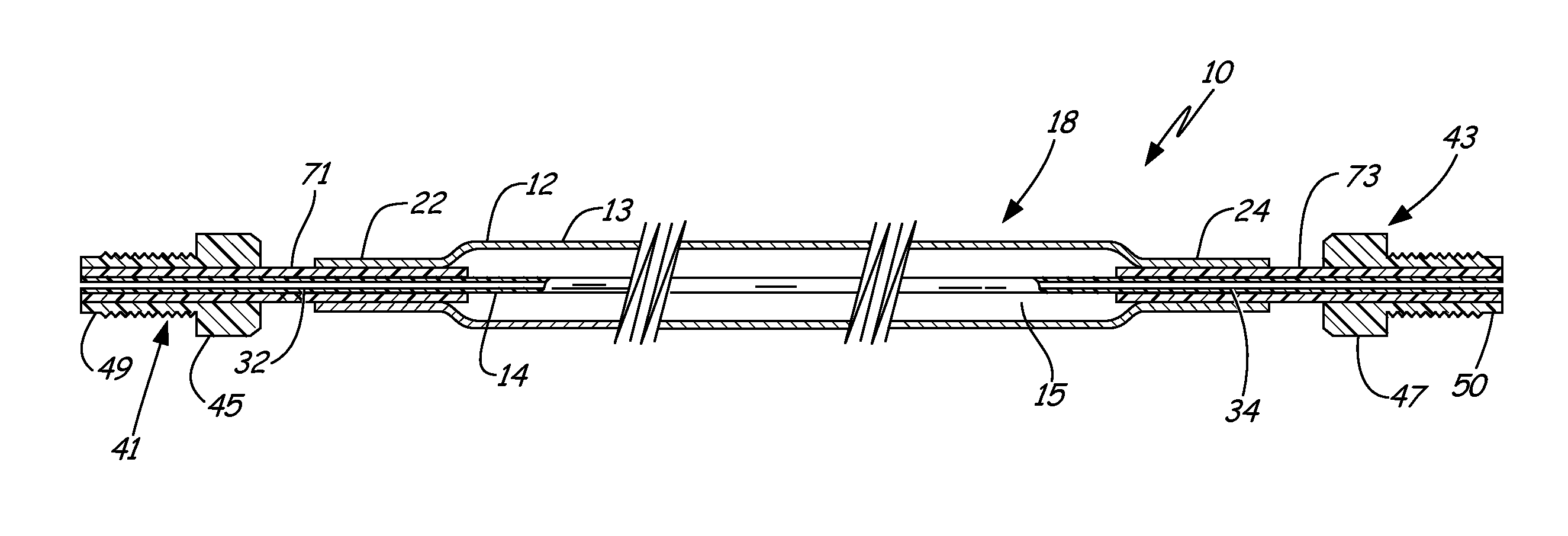
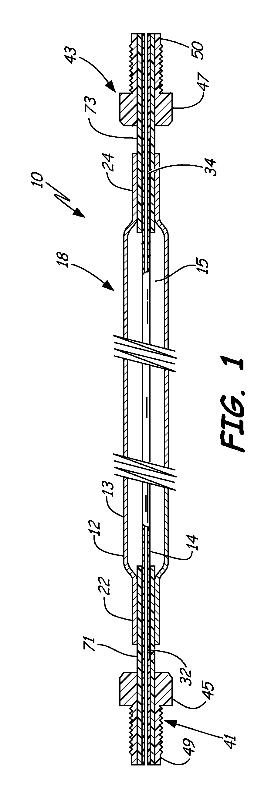
[0027]With reference now to the drawings, and first to FIG. 1, a flow through fluid treatment apparatus 10 of the present invention includes an outer shell 12 and an inner conveyance member 14 disposed within outer shell 12. In one embodiment, outer shell 12 defines a first chamber 15 therewithin, and through which inner conveyance member 14 extends.

[0028]In the illustrated embodiment, outer shell 12 includes an inlet end 22 and an outlet end 24, with inner conveyance member 14 having a corresponding inlet portion 32 a...


PUM

PropertyMeasurementUnit
diameteraaaaaaaaaa
pore sizesaaaaaaaaaa

Abstract

An elongated flow-through degassing apparatus includes an elongated gas permeable outer shell and one or more gas-permeable, liquid-impermeable elongated inner conveyance members extending within the outer shell and at least partially through a chamber defined within the outer shell. The apparatus also includes inlet and outlet junctions for securing the outer shell to the inner conveyance member. The outer shell exhibits a first permeance that is substantially greater than a second permeance of the inner conveyance member. The degassing apparatus may be sufficiently flexible so as to be readily manipulatable into desired configurations.

Description

CROSS-REFERENCE TO RELATED APPLICATIONS[0001]This application claims priority to U.S. Provisional Patent Application Ser. No. 61 / 533,429, filed on Sep. 12, 2011 and entitled “SUPERSATURATED FLUID DEGASSING,” the content of which being incorporated herein in its entirety.FIELD OF THE INVENTION[0002]The present invention relates generally to systems for degassing fluids from pressurized vessels, including for degassing pressurized fluidic reagents used for microfluidic systems, inks, semiconductor processing fluids and laboratory grade fluids. A flow-through transfer line degassing apparatus includes transfer lines which simultaneously act to passively degas fluids passing therethrough utilizing the driving force provided by the concentration differential between the pressurization gas and the atmospheric concentration of the pressurization gas, and to protect a degassing membrane from physical damage. The present transfer lines also exchange vapors and gasses with the atmosphere, and...

Claims


Application Information

Patent Timeline
Patent Type & Authority Applications(United States)
IPC IPC(8): B01D19/00B01D69/04B01D53/22
CPCB01D19/0031B01D63/02B01D63/06B01D2313/23B01D71/34B01D71/36B01D71/26
Inventor SIMS, CARL W.GERNER, YURILIU, QUAN
Owner IDEX HEALTH & SCI
Why Eureka
Try Eureka